3.
Installation.
The Nanovolt Amplifier should be mounted in such a
position that it is not subject to vibration.
The front panel controls,
(fig 2-8), and the inspection port on the left-hand side, (fig 2-9), should
be accessible.
a. Input connections.
The terminal cover plate may be removed after
unscrewing the knurled retaining screw. The copper link should be connected
between the terminals marked SERIES FEEDBACK or PARALLEL FEEDBACK according
to choice and the input connected to terminals 1 and 2 with output from
terminals 3 and 4. The characteristics of the two modes of operation are
listed below:
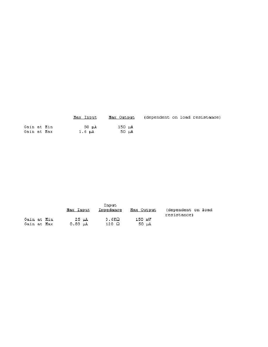
(1) Parallel feedback: This connection is predominantly useful when
the amplifier is to be employed as a null detector in bridge and
potentiometer work.
approximately 2. The maximum inputs that can be applied are as follows:
When greater sensitivity is required, the input connection can be made to
terminals 1 and 3 instead of terminals 1 and 2. This bypasses the 2 series
resistor and reduces the input impedance to between 0.01 and 0.2 from
minimum to maximum gain.
This connection is useful when working from low
impedance circuits.
(2) Series feedback.
This connection is primarily for applications
where the Model 9460A is to be operated as a linear voltage amplifier to
drive a potentiometer recorder or digital voltmeter.
It is also used in
high impedance circuits for null detection. The maximum inputs that can be
applied are as follows:
(3) The input circuit of the amplifier comprising the galvanometer
leads, terminals, and connections to the feedback components, is completely
of copper construction in order to avoid parasitic voltages.
It is
desirable that this principle be continued throughout that part of the input
circuit external to the amplifier.
The use of twisted pairs of bare
untinned copper wire with high quality insulation is recommended. Tinned or
stranded wire should be avoided. A length of suitable twisted shielded wire
(Guildline Type SCW) is supplied with the instrument.
(4) The terminal cover plate should always be in position when the
amplifier is in use in order to avoid drafts which may produce thermal EMFs at
the input terminals. The input and output leads should be accommodated in the
31


 Previous Page
