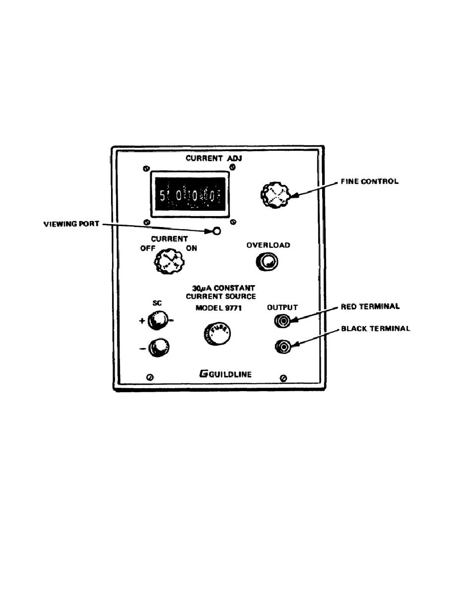
b. Terminals.
(1) SC terminals. These terminals are for connection to the standard
cell. Correct polarity is indicated by the "+" and "-" engraved next to the
positive and negative terminals respectively.
(2) CURRENT terminals.
The output current from the CCS appears at
these terminals. The voltage at the red terminal is positive with respect
to the black terminal.
Figure 2-6.
Front panel layout Model 9771
6.
Theory of operation.
The principle of operation is illustrated
in Figure 2-7.
The line supply is transformed, rectified, and smoothed
to give a dc supply at approximately 35 volts.
Current from this
source flows in the loop, consisting of the variable resistor, the
load, and a light-sensitive amplifier which functions as a light-actuated
variable resistance.
The voltage developed across the variable resistor
is arranged to be approximately 1.018 volt for all current values
within the range of the instrument.
This voltage is connected
in series opposition to a saturated standard cell and any difference
27


 Previous Page
