current but serve only as a logging facility in order to permit the
instrument to be reset to a particular current.
If desired, a chart or
graph may be prepared of current versus switch setting.
(2) OFF-CURRENT-ON.
This rotary switch has three positions which
give:
CURRENT circuit OFF, CURRENT circuit on, and galvanometer lamp ON.
The three positions are provided so that application of power to the current
circuit, and illumination of the galvanometer lamp always occur in the
correct sequence.
(3) OVERLOAD indicator.
This lamp is illuminated whenever the
overload relay becomes de-energized and disconnects the standard cell from
the current control circuitry.
The current is not controlled when the
OVERLOAD lamp is illuminated.
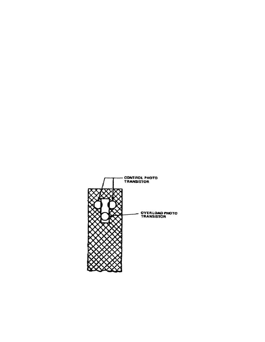
(4) Galvanometer zero adjust.
This knob is located on the side of
the CCS and is used to center the light spot on the photo transistors (fig
2-5).
(5) Viewing port. A small hole in the front panel immediately below
the thumbwheel switches enables the operator to view the position of the
galvanometer light spot.
(6) Fuse.
A 2A line fuse is located on the front panel of the
instrument.
Figure 2-5.
Light spot position
26


 Previous Page
