Learning Event 2:
DESCRIBE POTENTIOMETER DEVELOPMENT
1.
Early methods in standardization and calibration of dc instruments
stemming from standard cell-referenced potential difference, developed
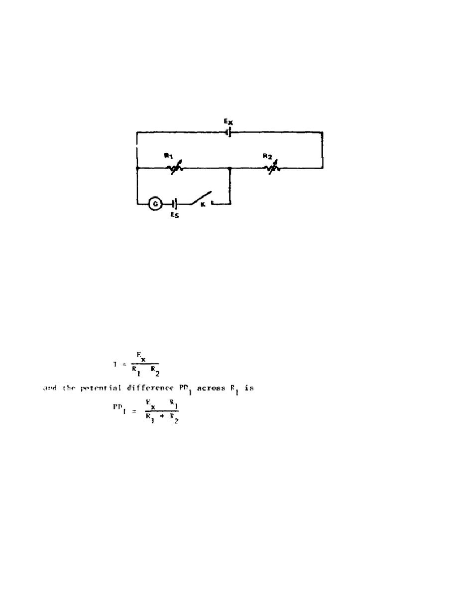
across a resistor, were resolved in the Poggendorf method shown
schematically in Figure 1-1.
Figure 1-1.
Poggendorf voltage comparison method
2.
The battery voltage Ex is to be determined from the accurately known
voltage of the standard cell Es and the standard resistors R1 and R2.
Referring to Figure 1-1, the assumption is made that R1 + R2 is sufficiently
high so that very little current flows through Ex and its internal fall of
potential due to internal resistance times the current is zero.
It is
assumed, further, that the full voltage Ex is the actual potential
difference developed across R1 + R2.
a. Hence, with the key (K) open, the current I in either R1 or R2 is
b. The standard cell Es is connected through a galvanometer (G), so
that, when the key is operated, the EMF of the cell will be in opposition to
PD1. For balance, R1 and R2 are varied, keeping their sum constant, until
2


 Previous Page
