10. Ground loops may result when the Model 887A, in which the chassis and
case are grounded, is connected to an instrument or signal-source ground at
a different potential. Current may flow in this completed circuit causing
erroneous meter readings. To avoid this condition the Model 887A should be
connected to the power source through a 3-pin to 2-pin isolation plug. This
disconnects the instrument from the external ground and effectively breaks
the ground loop circuit.
11. Common mode voltages may result when the circuit element to which the
instrument is connected is grounded through a second element. The situation
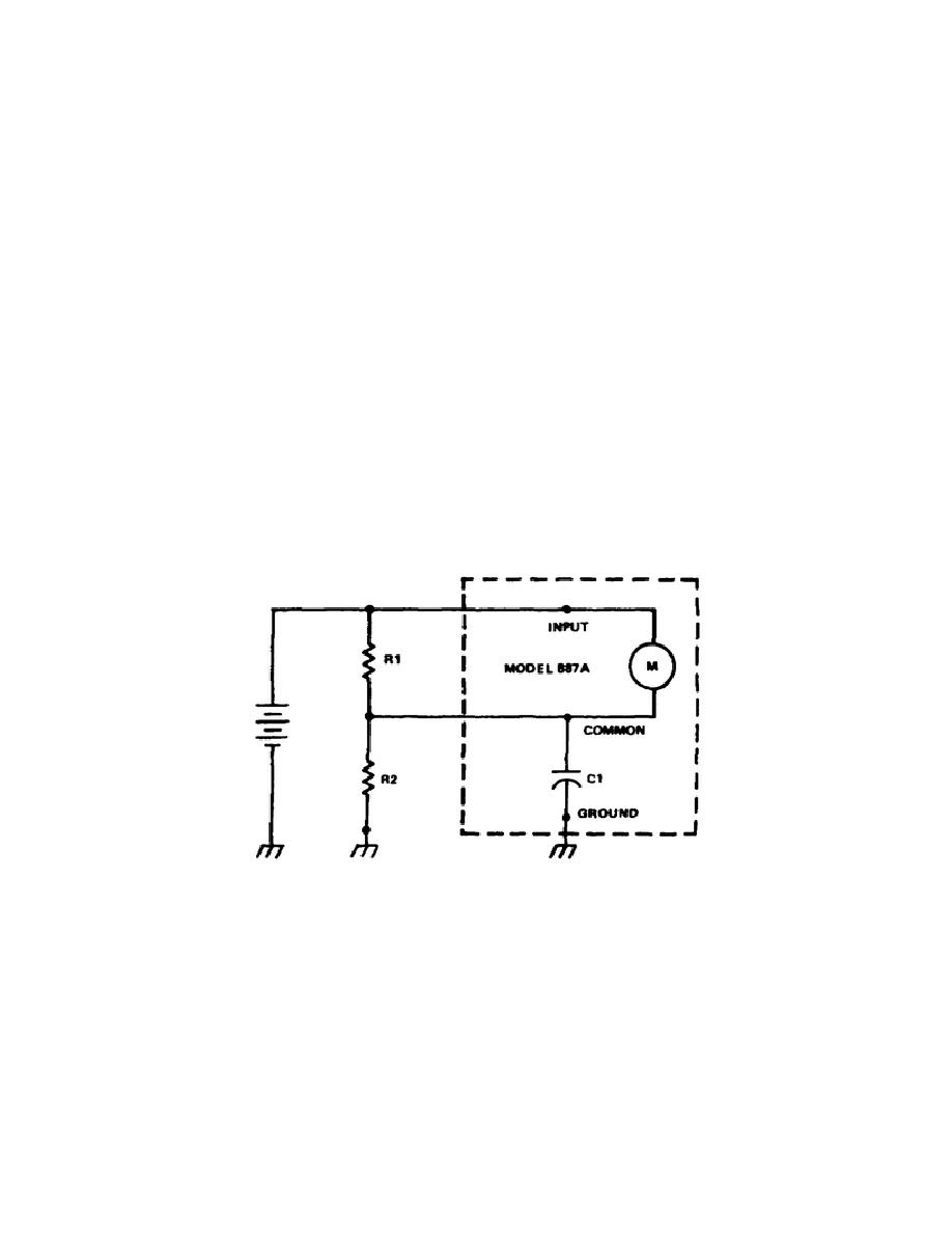
is illustrated in the simplified diagram of Figure 5-10. In this example,
if the COMMON and GROUND terminals are connected to an ac source, R2 is
shunted, increasing the current through R1 and causing an erroneous
measurement.
During dc measurements, error is determined by the leakage
resistance from the COMMON terminal to ground. The dc common-mode rejection
ratio while measuring voltages up to 1000V at a relative humidity of 70% or
less, is 5,000,000 to one or 0.2 uv from COMMON terminal to the GROUND
terminal. When making common-mode measurements, this capacitor may become
charged. This could lead to errors in succeeding low voltage measurements
(under 5 volts). Connect the shorting link from the COMMON terminal to the
GROUND terminal for a few seconds to discharge C1.
When measuring ac
common-mode voltages, a 3-prong to 2-prong line-cord isolation plug must be
used.
An ac load might otherwise be placed on the voltage source by
capacitor C1.
Figure 5-10.
Simplified voltmeter input circuit
12. The AC to DC Converter output voltage is 1.11 times the average value
of the ac input signal. Therefore, if the input is not a true sinusoid the
output will probably be in error.
The magnitude of the error will be in
proportion to the magnitude of the distortion and its phase and harmonic
relation to the fundamental.
Figure 5-11 indicates error magnitude as a
function of harmonic distortion.
105


 Previous Page
