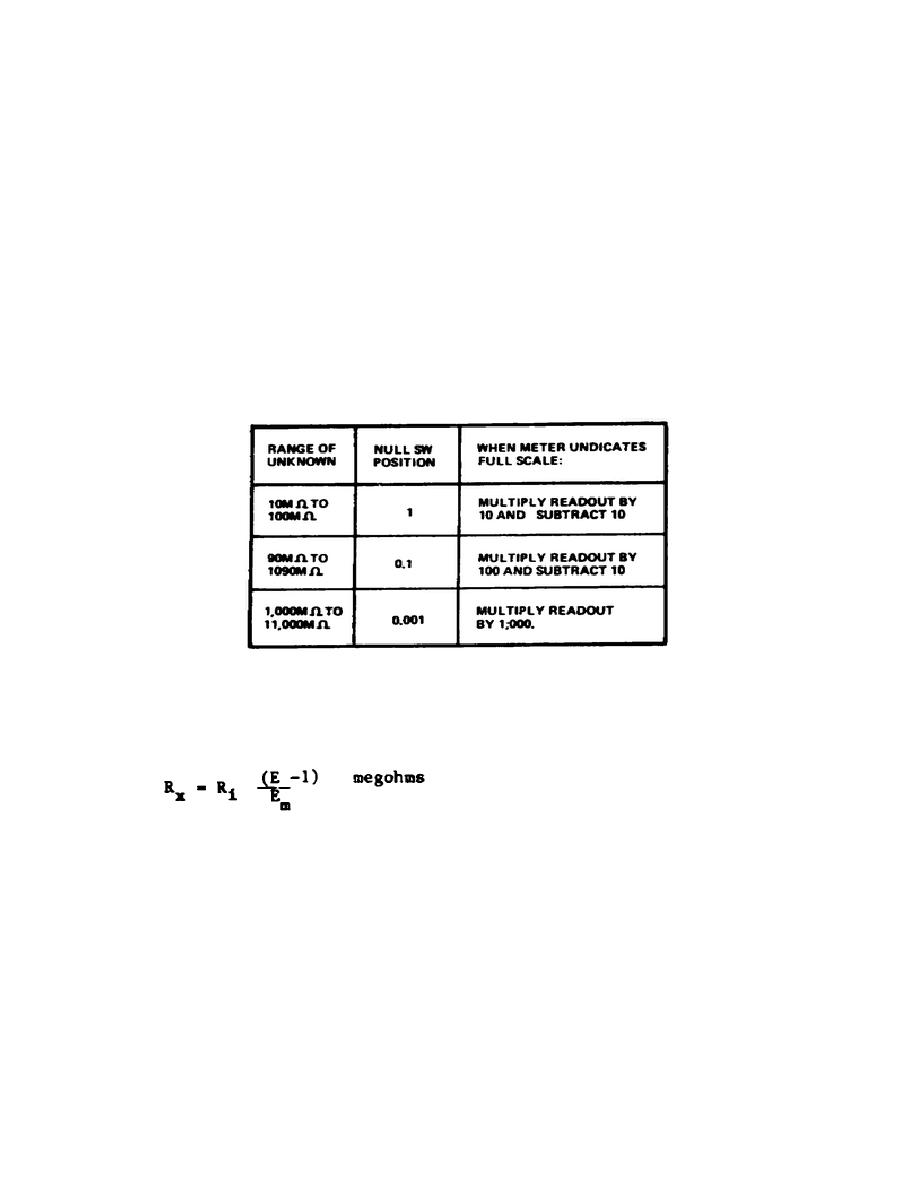
a. For the quick determination of resistance values in the range from
10 to 11,000 megohms the following procedure is followed:
(1) Correct meter zeroing is verified as in paragraph 4.
(2) The NULL switch is set to 1 and the RANGE switch to 10.
(3) The unknown resistance is connected to the INPUT and COMMON
terminals.
Short isolated leads are used to minimize errors due to lead
leakage resistance.
(4) The readout dials are adjusted for full-scale meter deflection
(-1.0). If full-scale deflection cannot be obtained with the NULL switch at
1, change it to 0.1 or 0.001.
(5) The value of the unknown resistance is determined from Figure
5-9.
Figure 5-9.
Measuring resistance with Model 887A
b. With the RANGE switch set at 10, the following formula may be used
to determine unknown resistance values.
Where:
Rx is the unknown resistance in megohms.
E is the voltage indicated on the readout dials
Em is the voltage indicated on the meter.
Ri is the input resistance of the TVM circuit in megohms. It is 10
for the 1 and 0.1 positions of the NULL switch and 1 for the 0.01
positions when the RANGE switch is set at 10.
104


 Previous Page
