(1) +EMF - This 2-position switch is of the locking toggle type
(i.e., pulling on the switch arm unlocks it and allows the switch position
to be changed) and serves to reverse the connections to the CCS terminals,
and hence reverses the output voltage from the potentiometer.
(2) X1 - EMF - X0.1 This 2-position switch is of the locking
toggle
type (i.e., pulling on the switch arm unlocks it and allows the
switch
position to be changed) and serves to change the measuring range
of the
potentiometer.
The range is 0 to 2.111,111,0V with the switch in
the X1
position and 0 to 0.211,111,l0V with the switch in the X0.1 position.
(3) GA ZERO. This continuously variable control is used to introduce
a back-off voltage which compensates for any thermal EMFs in the measuring
circuit.
(4) OSC. This lamp is connected to the modulator output and will be
illuminated during normal operation. An ampere-turn overload in the current
comparator will cause the lamp to become extinguished.
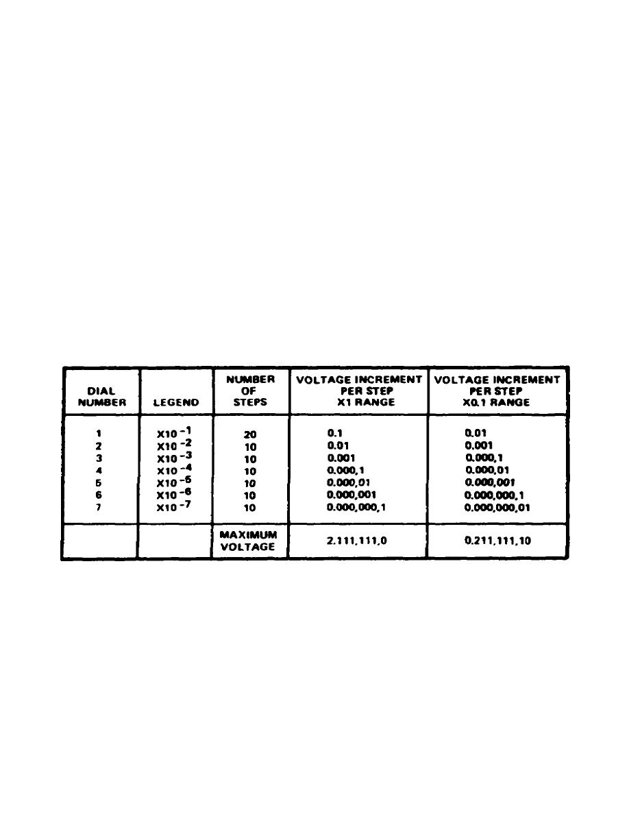
(5) Measuring dials. These seven dials set the potentiometer output
voltage in increments as shown in Table 2-1.
Each dial has 11 positions
(dial No. 1 has 21 positions) and the position numbers appear in the window
at the side of each dial.
Table 2-1.
Measuring dials
(6) GA SENS. This is the row of five pushbuttons, labelled 1 through
4, and R.
Each button selects a progressively greater galvanometer
sensitivity (number 4 being the most sensitive); and the button labelled R
reverses the galvanometer connections. Two dots are engraved on pushbutton
number 1. When these dots are at right angles to the line of buttons, any
button that is depressed remains depressed until another button is selected.
When the dots are parallel to the buttons, all the buttons are spring
return, and cancel automatically when released.
17


 Previous Page
