
frequency is obtained from the internal oscillator of the counter, often a
quartz crystal.
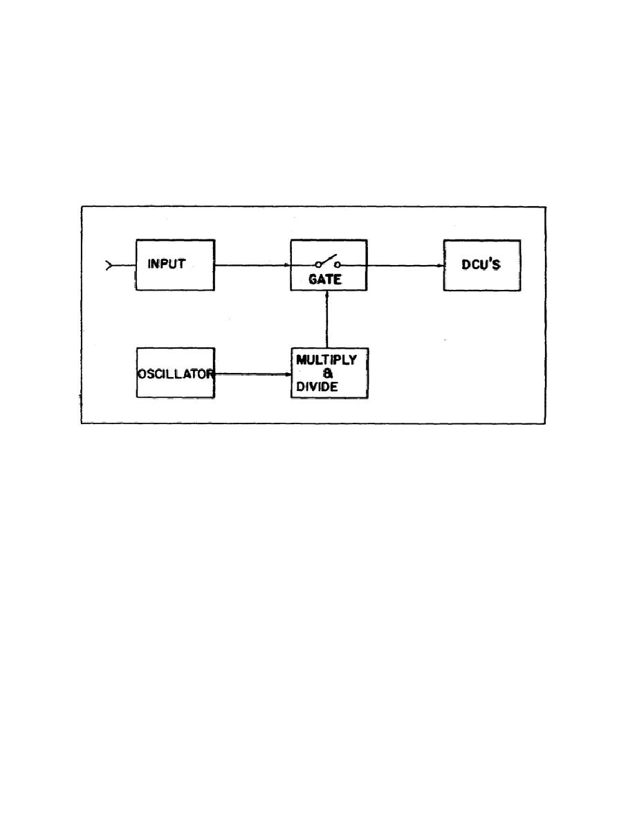
1.
ELECTRONIC COUNTER CIRCUITS
The principle of operation for most electronic frequency counters is
relatively simple when viewed in block form. Figure 1 is a block diagram
depicting the major circuits which comprise a basic frequency counter.
These are the Input circuit, Gate, Oscillator or Time Base, Multiplier and
Divider circuits, and the Decimal Counting Units (DCUs).
Figure 1.
Electronic counter block diagram.
a. Input Circuit. The signal input section accepts the input pulses of
suitable for driving the decimal counting units. The circuitry includes a
front panel located sensitivity adjust, an attenuator, an amplifier and a
Schmitt Trigger.
The sensitivity (level) control varies the amplitude of
the input signal, thereby controlling the gain of the amplifier and
providing a stable count.
The attenuator reduces the level of spurious
noise in the input to prevent its amplification which could result in
counting error.
The Schmitt Trigger shapes the amplified input waveform
into a series of rectangular pulses, maintaining the frequency of the input.
b. Gate Circuit.
The gating section serves two functions.
One of
these is to establish the duration of the counting interval to gate the
input signal through to the decimal counting section. The other function
2

 Previous Page
