
For example, using an external frequency of 1 Hz to open the gate and
selecting a time base of 10-6 to be passed to the DCUs, would result in a
count of 1,000,000 1 count. The accuracy of the reading is now increased
to 0.0001 percent. Compared to the frequency measurement of a 1 Hz signal
with a possible 100 percent error, this is a great improvement. The period
and frequency measurements are the two most widely used functions of an
electronic counter.
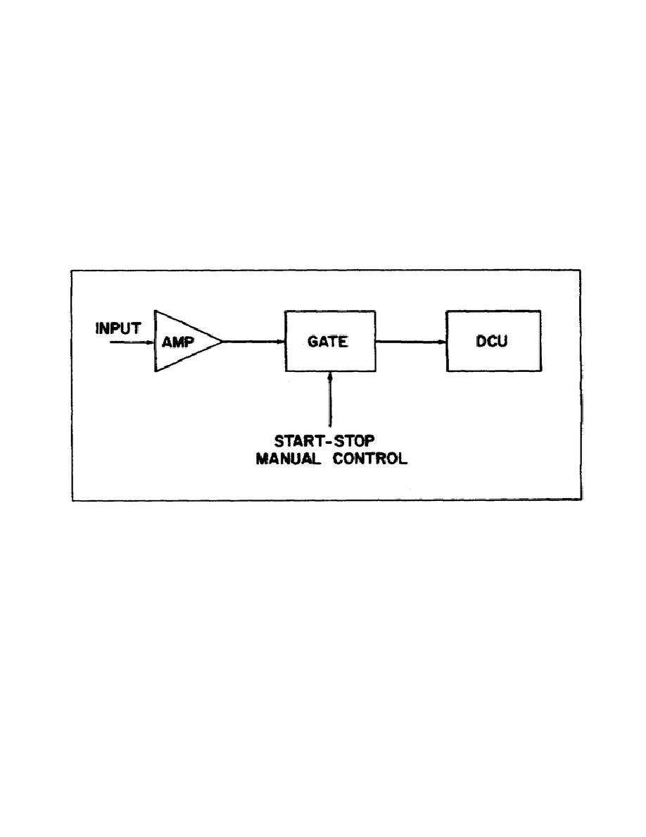
c. Totalizing. An electronic counter can be operated in the totalizing
mode, illustrated in figure 5, with the main gate flip-flop controlled by
the start-stop switch. With the switch at START, the gate is opened and the
DCUs will totalize the input pulses until the main gate is closed by
changing the switch to STOP. The display on the counter will then show the
pulses received during the interval between manual START and STOP.
Figure 5.
Totalize measurement.
d. Ratio Measurement.
The ratio of two frequencies is arrived at by
using the lower frequency signal for gate control and by having the higher
frequency signal counted as shown in figure 6.
By using the proper
transducers, ratio measurements may be applied to any phenomena, providing
the phenomena can be represented by sine waves or pulses. Measurements that
can be performed using the ratio method are clutch slippage, gear ratios and
frequency divider (or multiplier) operations.
e. Time Interval Measurement. Time interval measurements are similar
to period measurements; the only exception is that the trigger points on the
single waveform or waveforms are adjustable. Figure 7
6

 Previous Page
