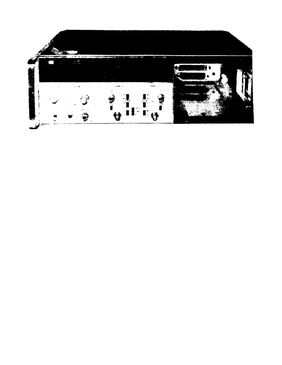
Figure 1.
Model 5345A electronic counter.
Two identical input channels are provided with switch selectable input
impedances of 1 megohm shunted by less than 30 pF and 50 ohms nominal. The
sensitivity varies from 20 mV rms for X1 attenuation to 200 mV rms for X10
attenuation settings.
b. Front and Rear Panel Controls, Connectors and Indicators. Tables 1
and 2 explain the purpose of each of the controls, connectors and indicators
associated with the Model 5345A.
Carefully study both tables prior to
proceeding to ensure your understanding.
c. Display. The counter uses a 12 digit display: 11 digits of data
and 1 digit for the minus sign. Unlike most counters, the number of digits
displayed in a measurement is not a function of the input frequency and is
not related to the FUNCTION switch.
The number of digits is constant for
each setting of the GATE TIME switch.
(1) Display Position.
When the DISPLAY POSITION switch is set to
AUTO, the counter automatically positions the display's least significant
digit in the right-most column.
Rotating the switch to each of its
counterclockwise positions (blue dots) shifts the decimal point, hence the
display, one place to the left. Once the switch is placed to any position
other than AUTO, the annunciator (k, M, n, etc.) stays fixed, regardless of
changing input frequency.
The annunciator remains fixed until the RESET
button is pushed or the FUNCTION switch setting is changed.
(2) Asterisk.
The asterisk lamp will light under any of four
conditions: overflow, underflow, factitious zeros, or insufficient oven
20


 Previous Page
