Table 2.
Rear panel controls and connectors (cont.).
(3) Arm Light. An illuminated ARM light indicates that Channel A is
not triggering.
The condition of this indicator should be observed when
adjusting the front panel controls for a first time measurement.
Insufficient amplitude of the input controls or improper setting of the
input controls (LEVEL, ATTEN, etc.) are common causes for the failure of the
GATE light to turn on.
(4) Gate Light. Once Channel A triggers, the ARM light turns off and
the GATE light turns on.
The GATE indicator lights during the time the
counter's event gate is open. For short-duration gate times, the GATE light
circuits include a 40 ms one-shot multivibrator to allow a visible flash of
the light.
The SAMPLE RATE control sets the time between flashes (or
measurement cycles).
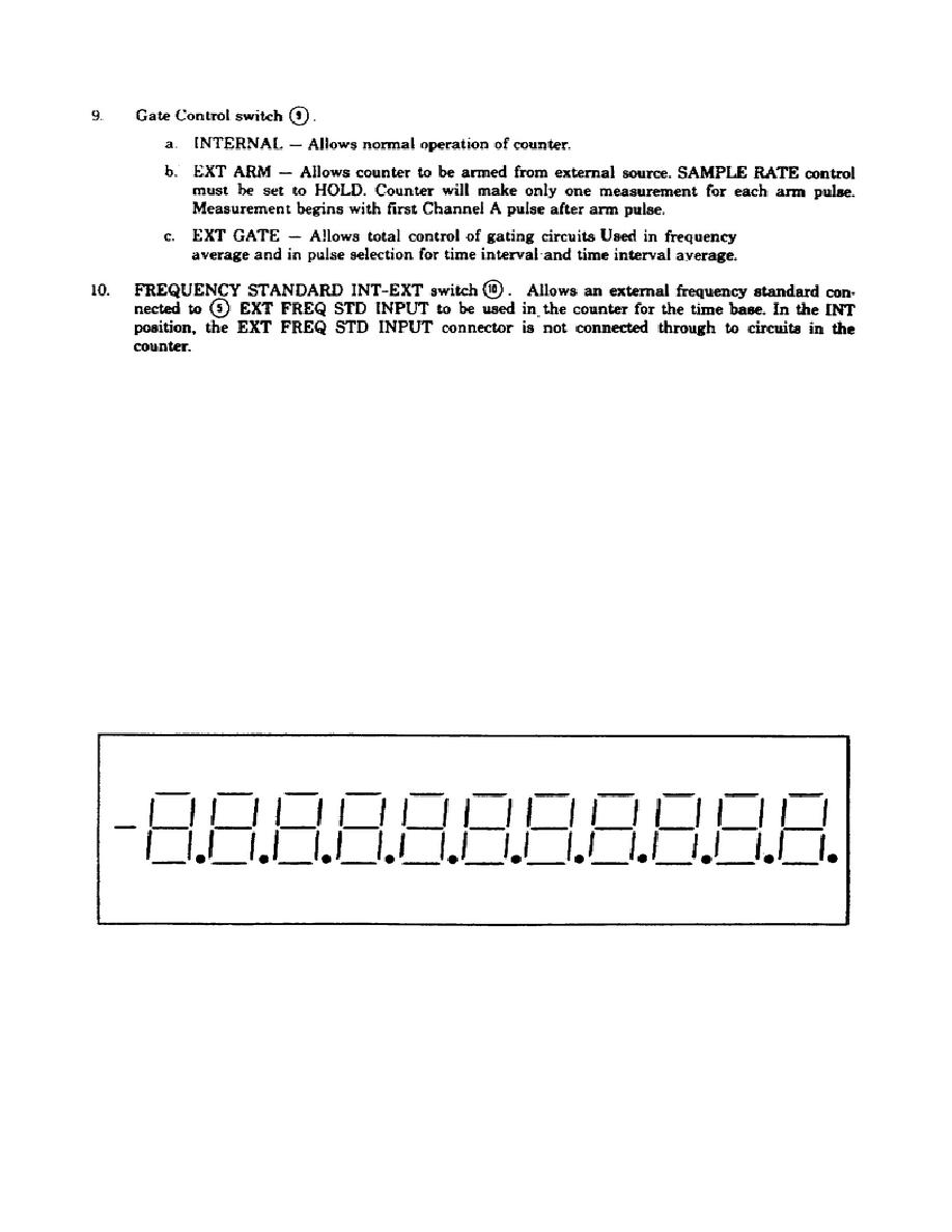
(5) Lamp Test. To ensure that all segments of the display are capable
of lighting, the counter provides a lamp test. The correct display should
appear like the representation shown in figure 2.
Figure 2.
Lamp test.
Lamp test occurs under several conditions:
24


 Previous Page
