ACCUM MODE START/STOP switch, located on the rear panel.
The two signals
are added (A+B) or subtracted (A-B), depending on the switch position. When
the Input Amplifier Control switch is set to CHECK, the counter always
selects (A+B).
A minus sign on the display indicates that during a subtraction (A-B)
the B events have outnumbered the A events.
With the switch in A-B, the
instrument functions like an up-down or reversible counter.
That is, the
counter will count down from a previously given positive number.
As an
example of this, assume that the A frequency is greater than the B frequency
and the switch is in A-B.
The display accumulates positive numbers at a
rate equal to the difference between the two input frequencies.
If the
frequency of B now becomes greater than A, the displayed count will decrease
towards zero, again, at a rate equal to the difference between the two
frequencies. Once the declining number passes through zero, the minus sign
lights and the display continues to accumulate.
(b) Scaled Output.
With the FUNCTION switch set to START and
SAMPLE RATE to HOLD, the counter scales (divides) the Channel A input
frequency by powers of 10.
This scaled signal is available on the rear
panel CHAD A SCALER OUTPUT jack. Although the display is not functioning,
the counter is accumulating.
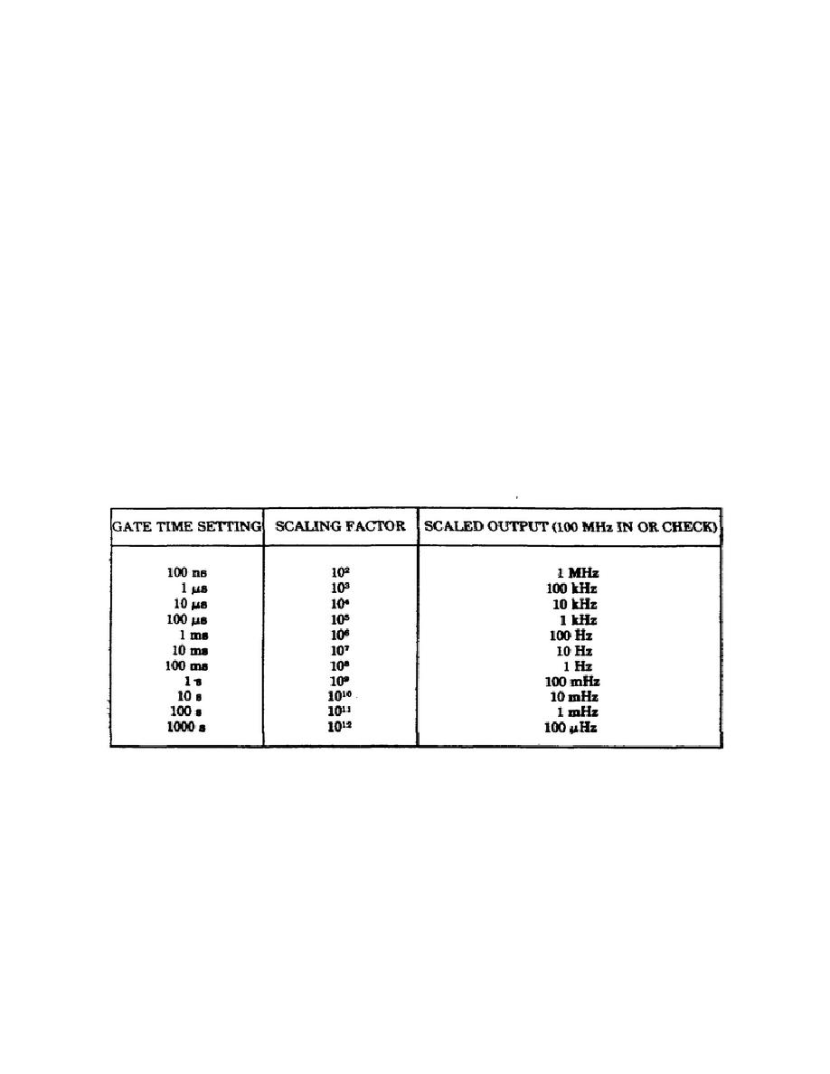
The GATE TIME switch controls the division
factor, as shown in table 3.
Table 3.
Scaler output for channel A.
The capabilities of the Model 5345A have been discussed in this lesson
only to the extent of their pertinence to your daily use requirements. It
would be to your distinct advantage at this point to operate the counter, if
there is one available, using this lesson material as a guide.
When you
feel that you fully understand the function of each of the controls,
indicators and connectors, you may take
28


 Previous Page
