4100 DTI uses Instrulab's patented RTD linearizing circuit with a dual slope A-D
converter with auto-zeroing, to provide an accurate, stable reading.
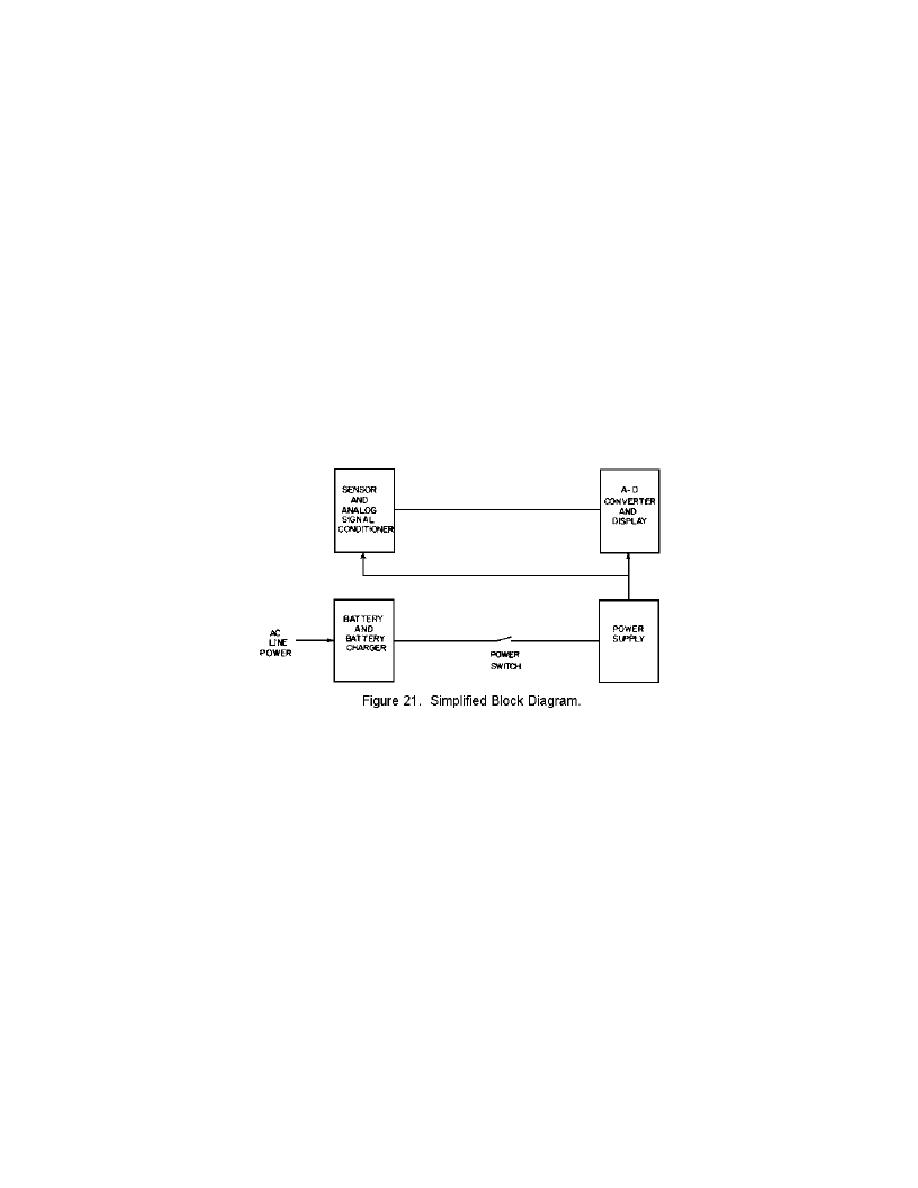
(2) Block diagram analysis.
Refer to the simplified block diagram, Fig. 2-21.
The 4100 DTI consists of four (4) sections:
(a) Sensor and analog signal conditioner
(b) A-D converter and display
(c) Battery and battery charger
(d) Power supply.
(3) Sensor and analog signal conditioner.
To minimize errors due to lead wire resistance, the sensor is supplied with a four
(4) wire lead configuration, two leads to each end of the RTD element. One pair
of leads (one to each end of the RTDF element) supplies a current which results in
a voltage across the RTD element. This voltage, sensed by the other pair of leads,
is converted to either a 1 millivolt per degree Celsius (for 0.1 degree resolution)
or a 10 millivolt per degree Celsius (for 0.01 degree resultion) signal for the A-D
converter.
his voltage is also converted into either a 1 Millivolt per degree Celsius or a 1 millivolt
per degree Fahrenheit analog output voltage.
(4) A-D converter and display (Fig. 22)
The basic 100 microvolt per LSD (least significant digit) sensitivity provides 0.1
degree Celsius resultion for the 1 Millivolt per degree Celsius input and 0.01
degree Celsius resolution for the 10 Millivolt per degree Celsius input. To provide
Fahrenheit readings, the input signal is multiplied by 1.8 (by extending the
integrate input state) and offset by 32 degrees (by presetting an Up/Down
counter). Refer to the A-D converter timing diagram, (Fig. 22). The A-D
converter has three states:
(a) Auto-zero
(b) Integrate input
(c) Integrate reference
(5) Auto-zero
This state starts at the end of the previous conversion cycle. If the unit is
connected to AC line power, the start of this state is synchronized to the line


 Previous Page
