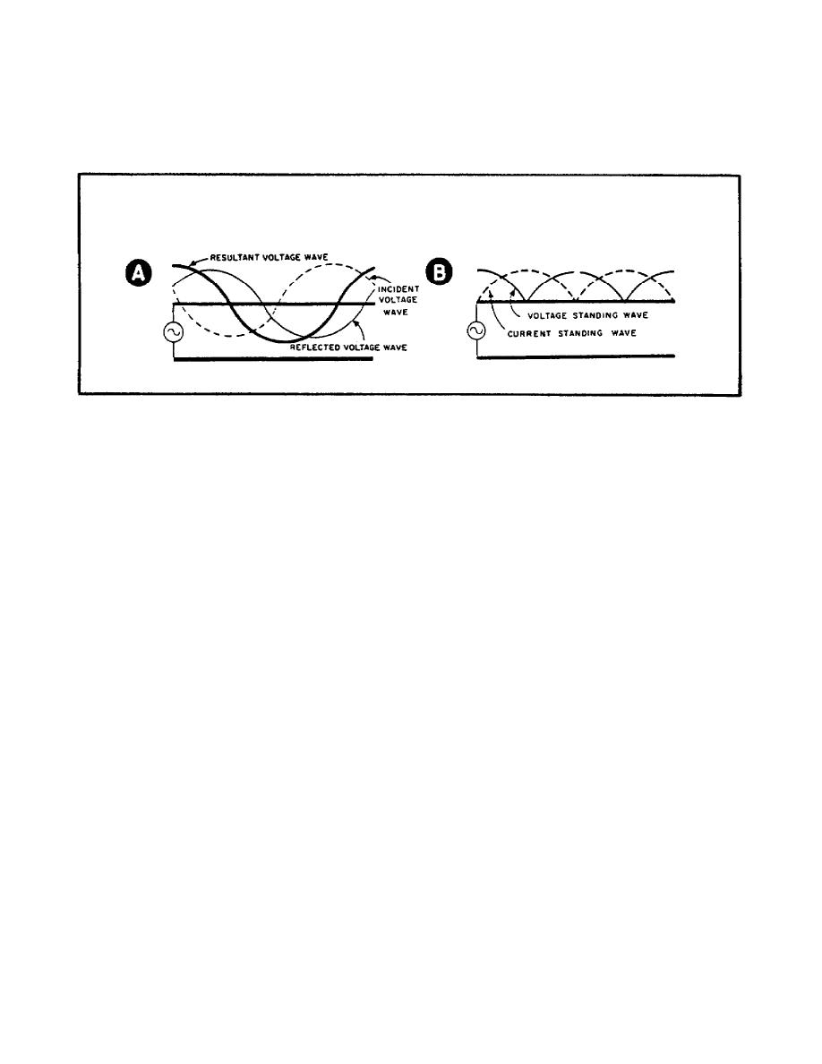
b. Part B of Figure 12 shows both current and voltage standing waves on
an open-end line. Notice that only one polarity is shown. The reason is
that when you used an AC meter to determine current and voltage on a
transmission line, it indicates amplitude but not polarity.
All the
readings are positive because of current rectification in the meter.
Figure 12.
Standing Waves of Current and Voltage on an Open-End Line.
23. Review of standing waves on an open-end line.
a. Current is zero at the open end.
b. Current is reflected out of phase.
c. Voltage is maximum at the open end.
d. Voltage is reflected in phase.
e. Standing waves of current and voltage are 90 degrees out of phase.
24. Standing waves on a shorted line.
a. Now, suppose we place a bar across the ends of the open line, thus
short-circuiting the transmission line as in Figure 13. The short circuit
presents a sudden impedance change to the incident RF energy. The impedance
change is so great that all of the RF energy is reflected back to the
source. Again standing waves result when the incident and reflected waves
combine.
16


 Previous Page
