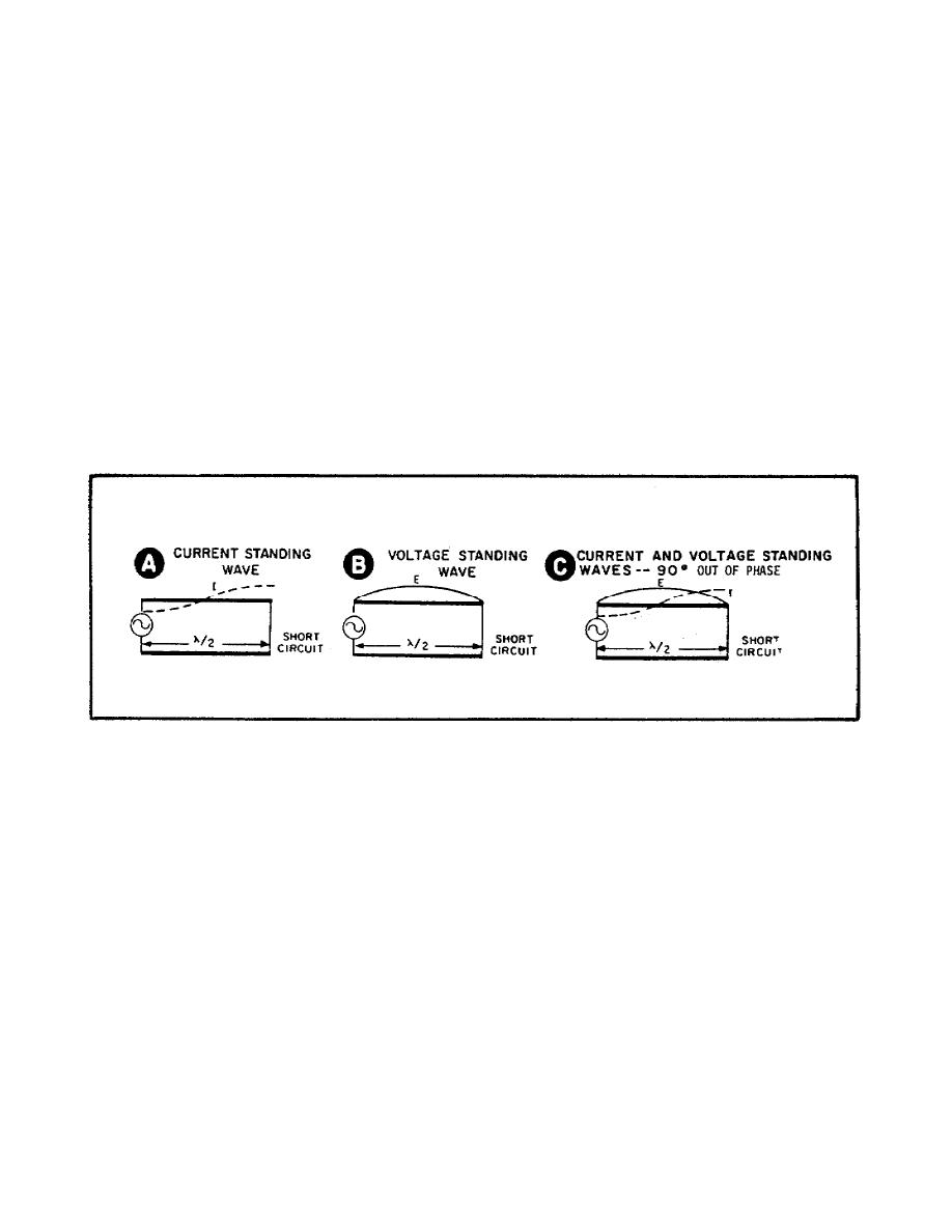
b. Part A of Figure 13 shows that the current is maximum at the short
circuit. As you know, this happens across any short circuit. The voltage,
however, is practically zero at the short circuits (Part B of Figure 13).
The current and voltage standing waves are 90 degrees out of phase (Part of
Figure 13). The conditions existing on a shorted line are as follows:
(1) Voltage is zero at the short.
(2) Voltage is reflected out of phase.
(3) Current is maximum at the shorted end.
(4) Current is reflected in phase.
(5) Standing waves of current and voltage are 90 degrees out of
phase.
c. Notice that these conditions are exactly opposite to those existing
on the open-end line (Figure 12).
Figure 13.
Standing Waves on a Shorted Line.
25. Measuring standing waves.
Now that we know what standing waves are and how they are produced,
the next thing to learn is how to measure them.
To make measurements on
telephone and power lines, we use ordinary AC measuring devices and no
difficulty arises.
But, when we try to make these same measurements at
ultra-high frequencies, the problem is different.
For instance, a wire-
wound calibrating resistor acts like an RF choke, while the familiar
resistors used in radio sets may behave like inductors or capacitors. And,
under certain conditions, an ordinary copper wire acts like an insulator.
So that, if we put a conventional AC meter in a UHF circuit, we may be
adding an unknown amount of capacitance or inductance. Our reading would be
completely incorrect.
17


 Previous Page
