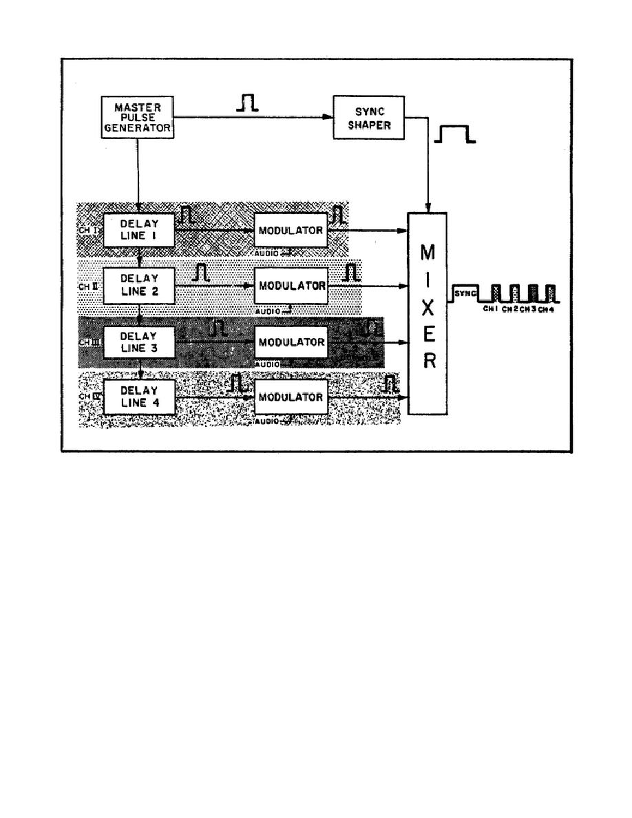
Figure 41.
Block Diagram of Multiplexing Delay Line.
22. How the delay line works in a TDM transmitter.
a. In Figure 41, the master pulse generator feeds pulses to the delay
line sections for each of twenty-three channels.
Because of space
limitations, only four channels are shown in the diagram. Then, each delay
line section feeds a pulse into the modulator in the modulator in the same
channel. Here's the important point, each delay line section introduces a
5.2-microsecond delay. This means that the pulse going to CH I modulator is
delayed 5.2 microseconds.
The pulse going to CH II modulator is delayed
10.4 microseconds because it passes through two delay line sections.
Similarly, the pulse fed to CH III modulator is delayed 15.6 microseconds
because it passes through the delay line sections of channels I, II, and
III.
b. This process continues until there are twenty-three pulses, each
separated by 5.2 microseconds in time, fed into the twenty-three different
Each modulator combines the voice signal with the pulse and
feeds the modulated pulse to the mixer. This produces a train of
47


 Previous Page
