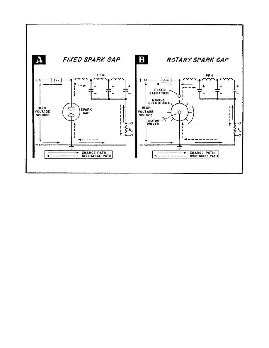
Figure 56. Early Radar Sets Used Spark Gaps to Discharge the PFN.
(2) The rotary spark gap shown in Part B of Figure 56 consists of a
set of moving electrodes rotating in front of one or more fixed electrodes.
The disk carrying the moving electrodes is mounted directly on the shaft of
the driving motor.
As the disk rotates, one of the moving electrodes
approaches the fixed electrode. The air between the two electrodes starts
to ionize.
A spark occurs and the PFN discharges through the very low
resistance of the spark gap.
By the time the next moving electrode
approaches the fixed electrode, the pulse-forming recharged network will
have been recharged.
(3) Although it is simple and can handle large amounts of power, the
spark gap, nevertheless, has some serious disadvantages:
(a) The
spark
gap
cannot
be
used
at
high
pulse
repetition
frequencies.
(b) It is unstable, that is, the firing time is uncertain.
(c) The electrodes become pitted and corroded quite easily.
70


 Previous Page
