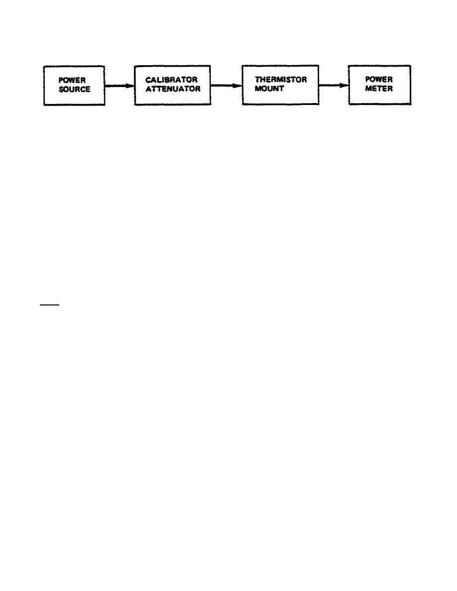
MM0474
Figure 1.
Typical power measurement connection.
(2) Power meter controls should be set to the following settings with
the power source operating in CW mode.
(a) MOUNT RESISTANCE
switch
to
the
position
corresponding
the
thermistor used.
(b) RANGE switch to 0.01 mW.
(c) ZERO and NULL controls to null meter as you learned in a previous
lesson.
(d) RANGE control to required position and CALIB FACTOR to position
stamped on label of thermistor mount.
c. Techniques
(1) Connect bolometer to source.
Note.
Make sure power out of source is less than maximum capability of the
setup.
(2) Power is read on meter in mW (or dBm if referenced on 1 mW range).
3.
CALIBRATION OF MODEL 431C POWER METER USING THE MODEL 8402 B CALIBRATOR.
a. Principle.
(1) Apply known DC current from an external DC power source.
The 8402B
calibrator can be used for this purpose also:
(2) Power meter should read full scale on range selected.
(3) Adjust controls on model 8402B to less than full-scale cardinal
points.
(4) Meter should track in accordance with indicated value on 8402B.
138


 Previous Page
