MM0474
b. Procedure
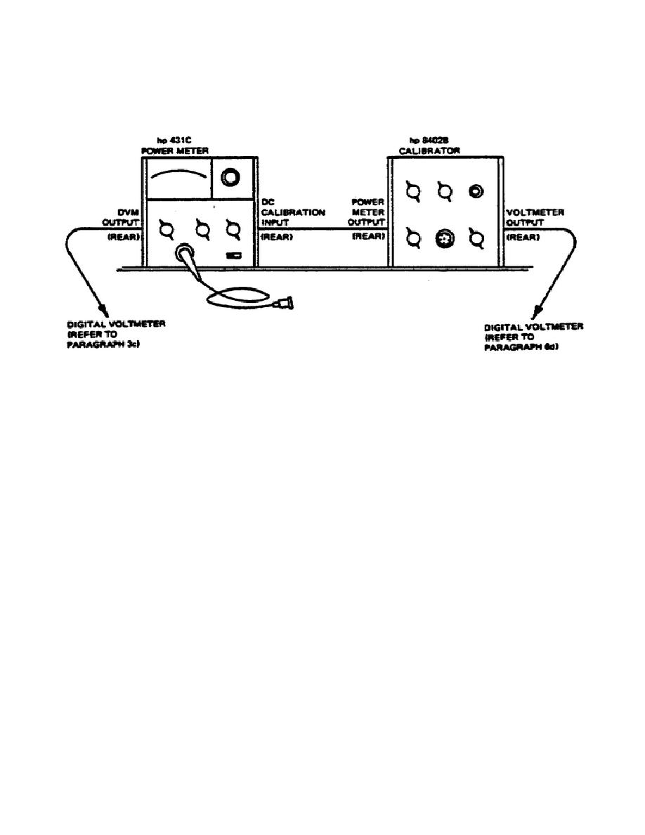
(1) Equipment should be connected as in DC substitution, Figure 2.
Figure 2.
Calibration of model 431C power meter.
(2) Technique.
(a) Zero and Vernier check.
1.
Connect DVM to DVM Output of 431C.
2.
Set MOUNT RES switch of H-P 431C to correspond to mount in
use.
3.
Turn RANGE switch of 431C to 0.01.
4.
Adjust zero control for 0.00 VDC on DVM.
5.
Turn RANGE switch of H-P 431C through ranges of 0.03, 0.1,
0.3, 1, 3, and 10 mW.
Voltmeter indication should remain
between -0.01 and +0.01 VDC.
If not, adjustment must be
made.
139


 Previous Page
