MM0474
a. After preliminary instructions have been followed, turn
on bridge and allow a 15 minute warmup period.
b. Bolometer mount should be attached to RF power source,
but with RF power off.
c. Place reference generator function
switch
in
NULL
position and V-REM-V switch to V. Record DVM reading.
d. Place V-REM-V switch to V function to RVG. Turn main
divider dial to indicate reading obtained in c. above and then tune ten-turn
dial until DVM indicates 0.0000. This indicates zero difference between bridge
and reference generator, i.e., null condition. Null both bridges in the same
manner.
e. Place reference generator No. P1 function switch to RVG
position (full ccw). V-REM-V to V.
f. Place reference generator No. P2 function switch to STAB
position (full cw). V-REM-V to V.
g. Change switch (9) to direct power to the power standard
assembly and adjust to 9 mW output as read on 431C.
h.
Disconnect thermistor mount and connect uut thermistor
connection B.
3.
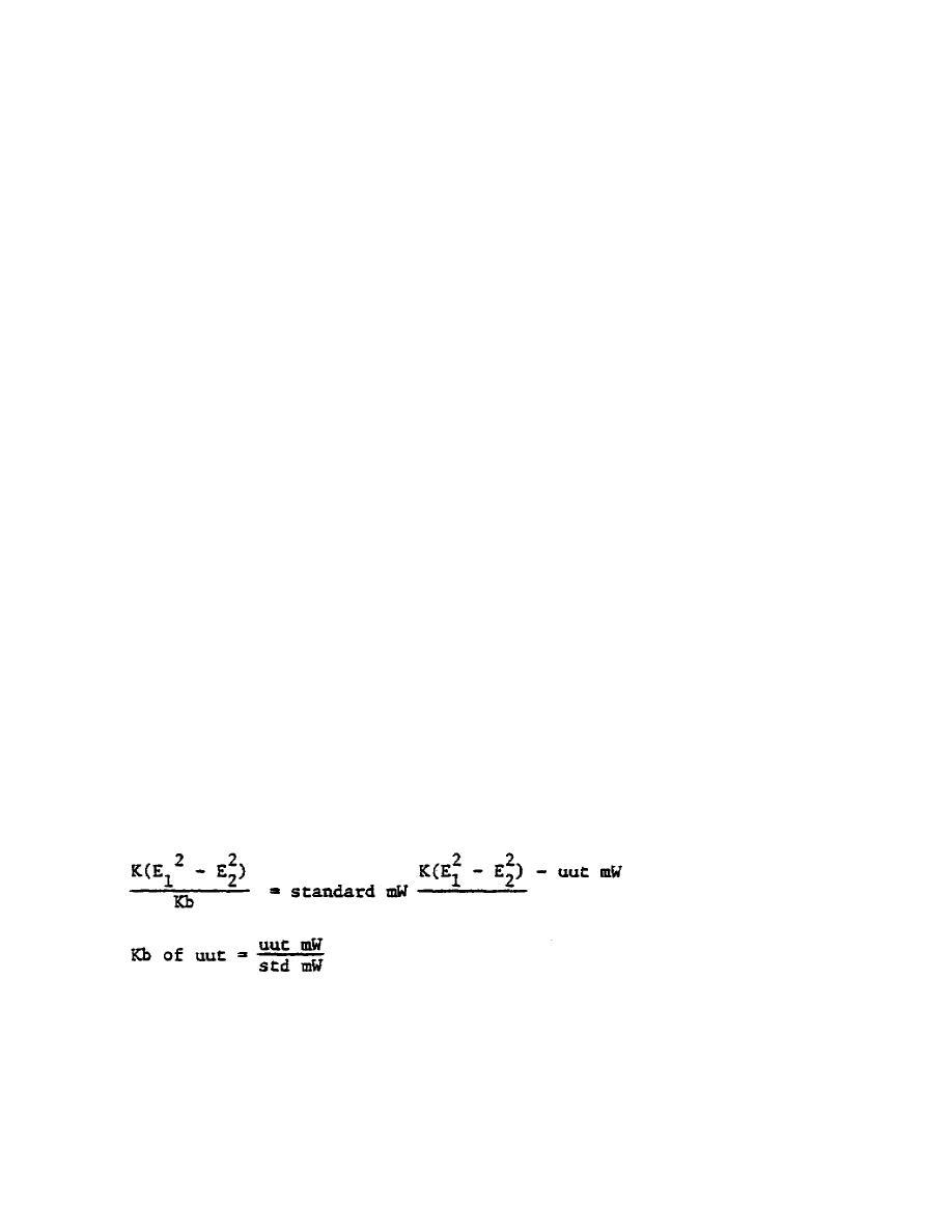
Determining "Kb" factor.
a. Set knife switch (17) to P1 position and switch (9) to
POWER ON - Record voltmeter reading as E2 of standard.
b.
Turn switch (9) to POWER OFF, record voltmeter reading
and record as E1.
c. Repeat d(1) and d(2) with knife switch in P2 position and
record as E1 and E2 of uut. Calculate the power using the expression:
150


 Previous Page
