
MM0474
(i) The calculated power should be between 0.89 and 0.91 milliwatts.
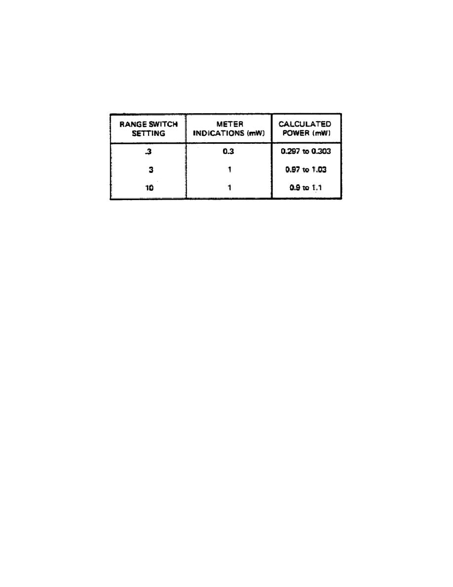
(j) Step (d) through (h) can be repeated for each position listed in
Table 2.
Table 2.
Meter Accuracy Test.
(2) Recorder Output Test
(a) For this test a digital voltmeter should be connected to the test
instrument RECORDER output connector.
(b) With the test instrument RANGE switch set to position .1, the
coarse zero control should be adjusted for a full scale indication on the test
instrument meter.
The digital voltmeter should indicate between 0.9995 and
1.005 volts dc.
(3) Calibration Factor Test
(a) With the test instrument CALIBRATION FACTOR switch set to 88%,
adjust the coarse zero control for 1.000 volt dc on the digital voltmeter.
(b) Set the CALIBRATION FACTOR switch to positions listed in Table 1.
The digital voltmeter will indicate within specified limits for each position.
6.
POWER MEASUREMENTS USING NBS II POWER BRIDGE WITH POWER STANDARD ASSEMBLY
(MOUNT AND DIRECTIONAL COUPLER).
a. Measurement principles: DC substitution technique is employed to
manually match a bridge voltage that has been automatically nulled by
integrated circuitry. After match has been accomplished, difference from null
condition (no power) is determined, and power is calculated. Overall accuracy
obtainable is better than .5%.
147

 Previous Page
