MM0474
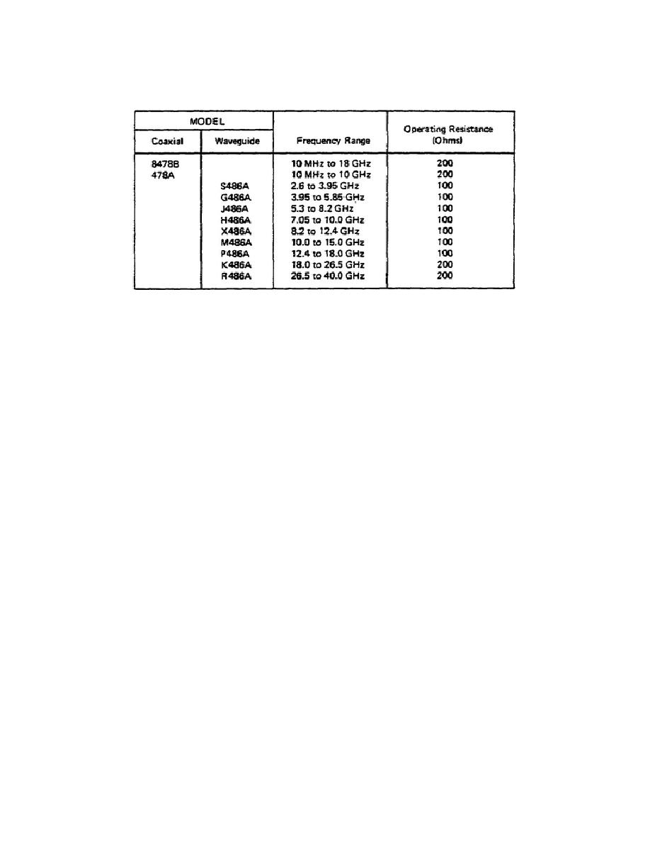
Table 2.
Model 431C Thermistor Mounts
measured with these mounts in 50 ohm coaxial systems from 10 MHz to 18 GHz, and
in waveguide systems from 2.6 GHz to 40 GHz. Full-scale power ranges are 10
microwatts to 10 milliwatts and -20 dBm to +10 dBma. Extended measurements may
be made to 1 microwatt to -30 dBm.
The total measurement capacity of the
instrument is divided into seven ranges, selectable by a front panel RANGE
switch.
(2) ZERO and VERNIER zero-set controls zero the meter. Zero carryover
from the most sensitive range to the other six less sensitive ranges is on the
particular range to be used. When the RANGE switch is in the NULL position,
the meter indicates inherent metering bridge unbalance, and a front panel NULL
screwdriver adjustment is provided for initial calibration.
(3) The CALIB FACTOR switch allows the introduction of discrete amounts
of compensation for measurement uncertainties related to SWR, and measurement
errors caused by substitution error and thermistor mount efficiency.
The
appropriate selection of a Calibration Factor value permits direct meter
reading of the RF power delivered to an impedance equal to the characteristic
impedance (Zo) of the transmission line connecting the thermistor mount to the
RF source. Calibration Factor values are determined from the data marked on
the label of each 8478B, 478A, or 486A thermistor mount.
(4) The Model 431C has a DC CALIBRATION jack on the rear panel that can
be used for DC substitution method of power measurement. DC substitution is an
extension of the power measurement technique normally used. Through the use of
DC substitution, instrument error can be reduced from a nominal value of 1% to
0.16% of reading, or less, depending on the care taken in procedure and
accuracy of auxiliary equipment.
12


 Previous Page
