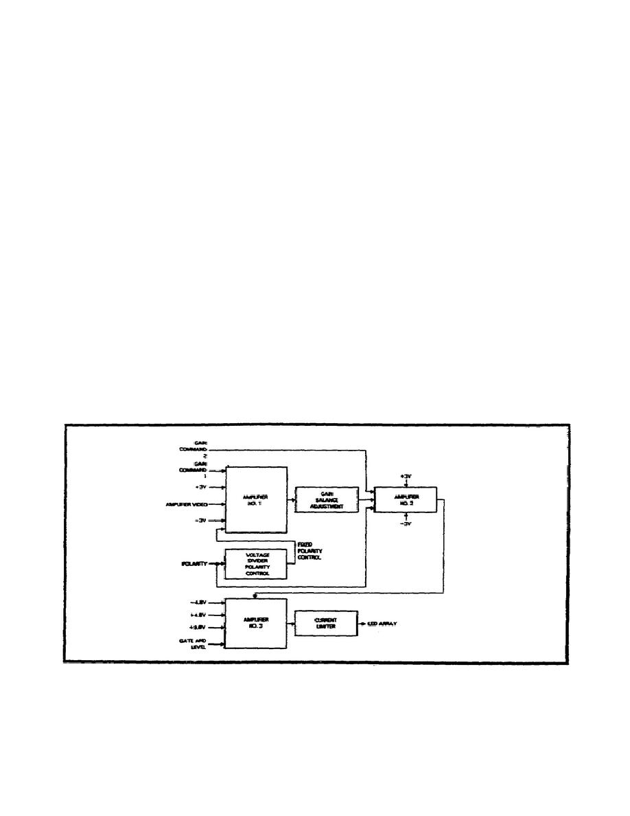
Video Postamplifier.
The video postamplifier control driver (Figure 2-19) provides 60
channels of additional signal amplification, variable gain control,
video gating, and drive current for the LED array. Each of the three
video postamplifier control drivers contains 20 channels of video
amplification.
Since operation of each of the 20 channels is the
same, operation of only one channel is described.
The amplifier
video signal is input to amplifier No. 1. The voltage gain of this
stage is controlled by gain command 1. The polarity control applied
to amplifier No. 1 is fixed by the voltage divider polarity control
circuit. The amplifier video signal from amplifier No. 1 is applied
through the gain balance adjustment circuit to the input of amplifier
No. 2.
Gain command 2, a variable gain control voltage level,
controls the gain of amplifier No. 2. The output from amplifier No.
2 is applied to amplifier No. 3. Amplifier No. 3 provides the final
stage of video signal amplification. The gate and level function is
used to adjust the average brightness during the active scan period
and to shut off the video channel during the scan mirror turnaround
periods to conserve power.
This stage requires two positive
supplies, +9.6 and +4.8 VDC, and a negative supply, -4.8 VDC.
The
current limiter circuit provides current limiting in case a short
circuit occurs across the output of a video channel.
The current-
limiting circuit provides the video drive signals that are applied to
the LED array.
Figure 2-19.
Video Postamplifier.
35
MM4812


 Previous Page
