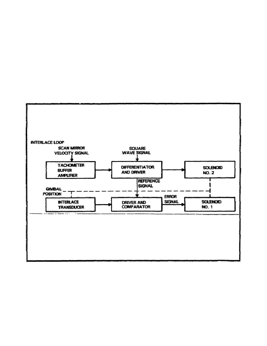
Interlace Loop.
The interlace loop (Figure 2-16) is a position servo loop.
The
position of the gimbal is determined and positioned by the scan
mirror velocity.
The reference signal is developed by the
differentiator and drive circuit.
The gimbal position signal is
amplified and compared with the reference signal by the driver and
comparator circuit which generates an error signal. The error signal
is used to operate solenoid No. l and is balanced with the signal
from the differentiator to operate solenoid No. 2.
Both solenoids
hold the interlace gimbal in the proper position during the scan
sweeps.
Figure 2-16.
Interlace Loop.
32
MM4812


 Previous Page
