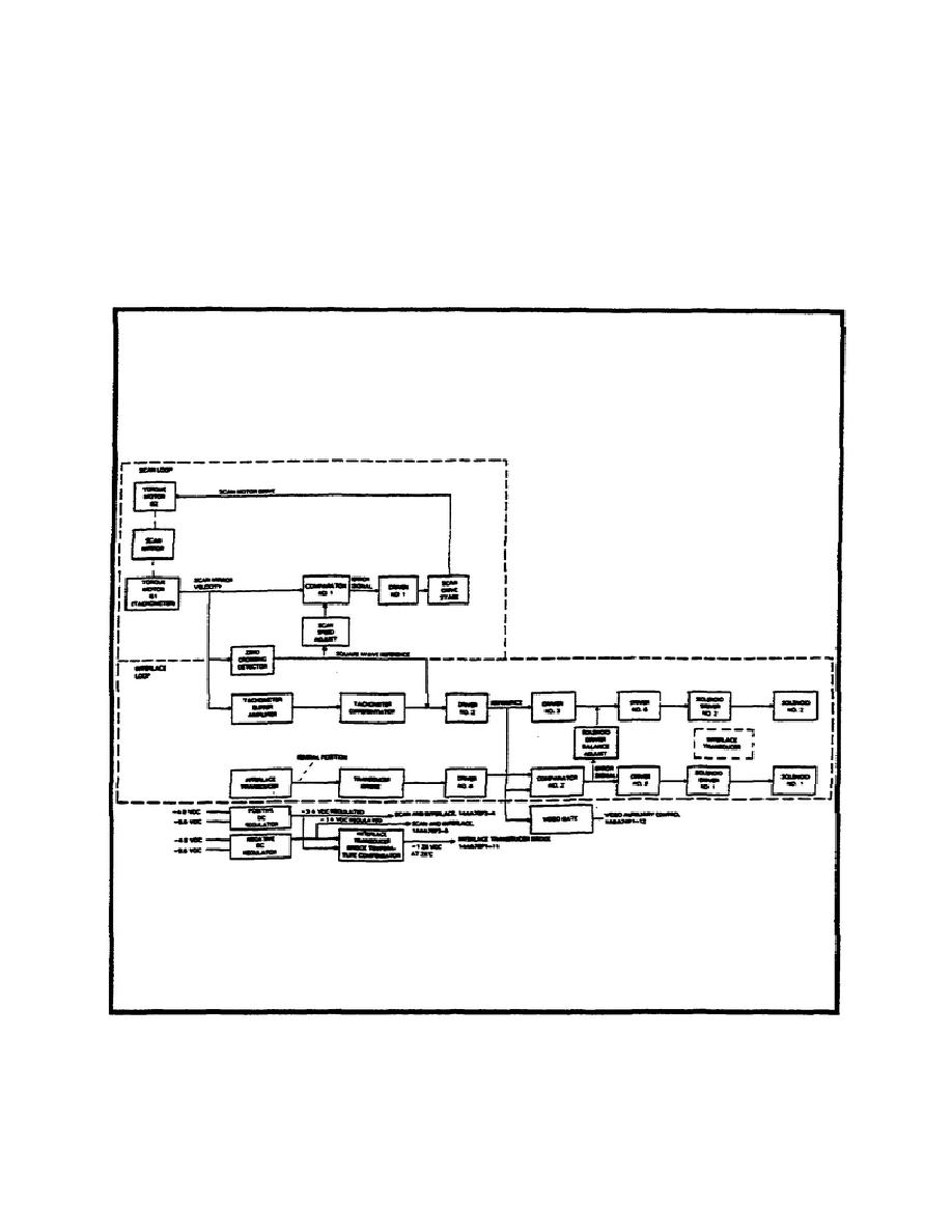
Scan and Interlace Circuitry.
The scan and interlace circuitry (Figure 2-14) consists of two
control loops: the scan loop and the interlace loop. The scan loop
is a rate servo loop using the scan mirror's bottom torque motor B-1
as a tachometer for scan velocity information. The interlace loop is
a position servo loop using two magneto-resistive transducers for
gimbal position information to synchronize shift of the interlace
gimbal solenoid at the end of each scan of the mirror.
Figure 2-14.
Scan and Interlace Loop.
30
MM4812


 Previous Page
