Scanning Mirror.
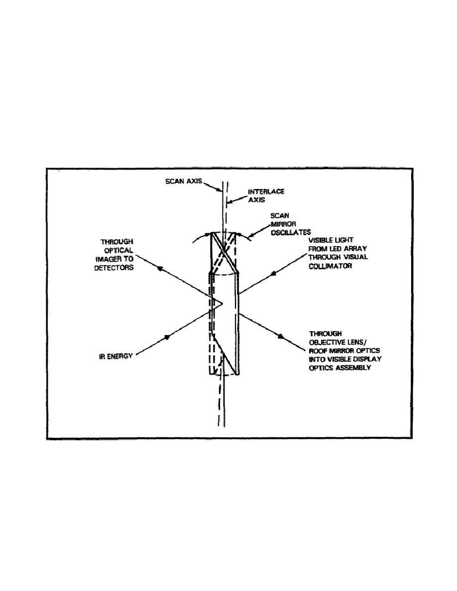
The scan mirror (Figure 2-12) oscillates about the scan axis. As the
scan mirror reaches one end of its travel, the scan axis tilts. As
the scan mirror reaches the opposite end of its travel, the scan axis
tilts to its original position. This action creates a 2:1 interlace
scan pattern. The front side of the scan mirror directs incoming IR
energy through the optical imager onto an array of IR detectors. The
back of the mirror receives the visible light output of the LED array
from the visual collimator and reflects it through the objective
lens/roof mirror optics into a visible display optics assembly.
Figure 2-12.
Scanning Mirror.
28
MM4812


 Previous Page
