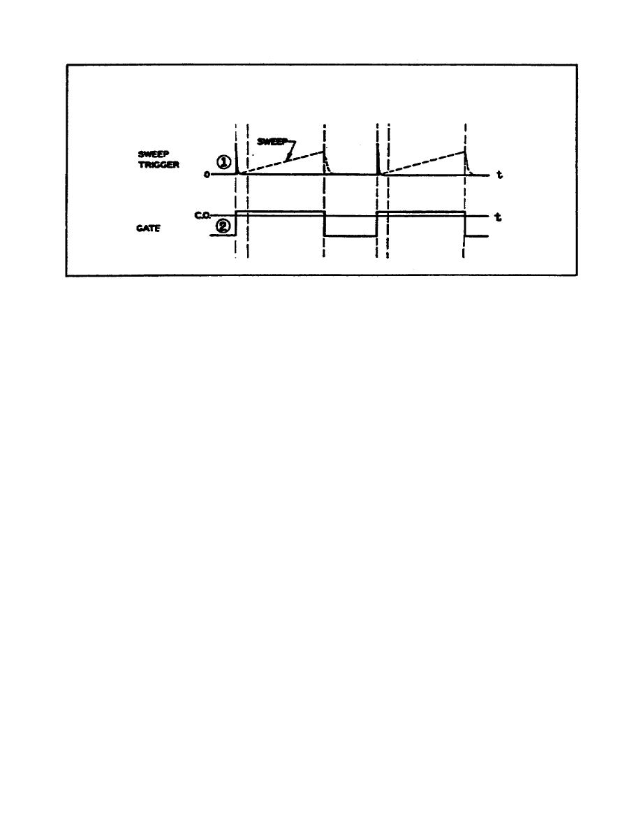
Figure 11. Time relationship of timing pulses
(a) Sweep trigger. The timer starts the sweep in the
indicator circuits. The timing pulse is normally in the form of a
sweep trigger where it occurs simultaneously with the input signal so
that the beginning of the sweep and the beginning of the input signal
coincide.
(b) Gate. The gating voltage limits the length of time the
sweep appears on the screen. If the sweep were to remain in
operation during the period between pulses, input signals might
appear on the sweep retrace, and the operator might become confused
when interpreting the signals. The negative portion of this waveform
is commonly called a blanking pulse. The portion of the waveform
below the indicator tube's cutoff (CO) point blanks out the electron
beam from the tube's cathode.
(2) Typical radar timer block diagram. The timer performs
the functions of establishing the pulse repetition frequency of a
radar system and of synchronizing the actions of the other components
to the transmitter. The block diagram in Figure 12 shows a
combination of circuits that can be used to develop the trigger
pulses and the gating voltages required in a radar system. The
waveforms produced by the circuits represented in Figure 12 are shown
in Figure 13.
18


 Previous Page
