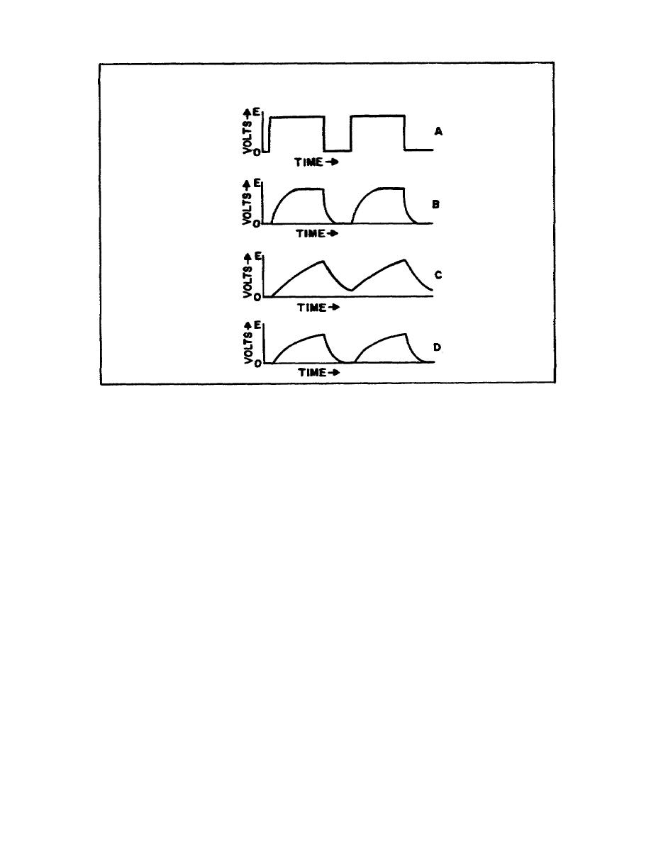
Figure 21. Response of a series RL circuit to an ideal
rectangular pulse
b. In Figure 21A, the rectangular pulse represents the input
21B, C, and D are taken across C in an RC circuit and across R in an
RL circuit. In Figure 21B, the output voltage reaches a value equal
to E a short time after the input pulse is applied, and decays to
zero after the input pulse is removed. This is the result of a
shorttime constant in relation to the width of the input pulse and
the rest time between the pulses. In Figure 21C, the output voltage
reaches a value equal to E more slowly and does not decay to zero
before the next input pulse is applied. This is the result of a
longtime constant in relation to the rest time between pulses. In
Figure 21D, the output voltage does not reach a value equal to E but
does decay to zero before the next input pulse is applied. This is
the result of a longtime constant in relation to the width of the
pulse.
Section II. CHARACTERISTICS OF RC AND RL TIME CONSTANTS
15.
GENERAL.
a. In a series RC or RL circuit, the time constant depends upon
the value of the component parts since the time constant formula is
TC = RC for an RC circuit, and TC = L/R for an RL
48


 Previous Page
