d. Tetrode Tubes. Placing a second grid, known as a screen grid, between the
control grid and the plate results in a tetrode tube (four elements). This grid is
added specifically to accelerate electron flow in the tube.
A positive voltage,
approximately the same as the plate voltage, is applied to the screen grid to
attract the electrons that are emitted by the cathode. The
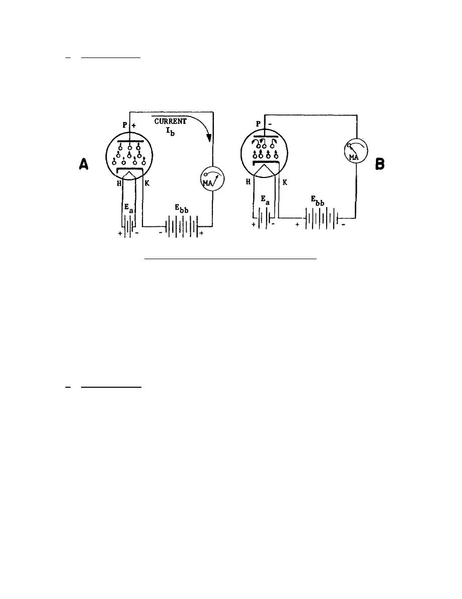
Figure 1-2.
Electron flow in a diode.
screen grid, being a coil of wire, will attract only a small number of electrons.
The majority of the electrons pass through the screen grid at an accelerated rate,
thus increasing the amount and velocity of electron flow.
The small number of
electrons attracted to the screen grid form a current known as screen grid current.
The insertion of the screen grid also reduces the internal capacitance of the,
tube, permitting operation at higher frequencies than the triode. Because of the
high velocity of the electrons in a tetrode, some of them bounce off the plate and
return to the screen grid. This undesirable effect is known as secondary emission,
and the current is called secondary current.
e. Pentode Tubes. Adding a third grid, known as a suppressor grid, results
in a pentode (five elements) and reduces secondary emission. The introduction of
the suppressor grid further reduces the internal capacitance of the tube,
permitting the use of higher frequencies. The function of the other elements are
the same as in the tetrode. By operating the suppressor grid at the same potential
as the cathode, the electrons from the plate due to secondary emission are repelled
back to the plate by the suppressor grid. Since the electrons cannot return to the
screen grid, screen grid current is reduced, and plate current is greater than that
of a tetrode.
4


 Previous Page
