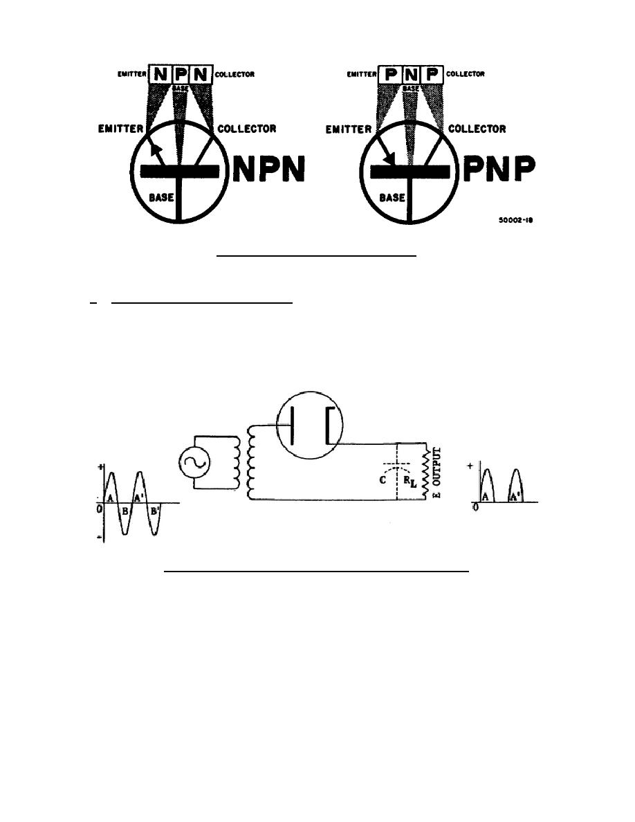
Figure 1-4.
Transistor symbols.
1-3.
APPLICATION OF ELECTRON TUBES AND SOLID-STATE DEVICES IN ELECTRONIC CIRCUITS
a. Rectifiers and Power Supplies.
(1) A typical diode tube half-wave rectifier circuit is shown in figure 1-
5. This circuit converts the ac input voltage into a dc voltage. The
unfiltered output of this circuit is shown in A of figure 1-6.
The
effects of adding filter capacitor C to the circuit is shown in B of
figure 1-6. Additional filtering will further smooth the dc.
Figure 1-5.
Diode used as a half-wave rectifier.
(2) Figure 1-7 shows a typical full-wave rectifier power supply. Section A
of the twin diode converts one-half the input cycle to a dc pulse when
plate A is positive, and section B converts the other half-cycle when
plate B is positive. The result is an output frequency twice that of
the output from the half-wave rectifier.
The higher frequency is
easier to filter to a steady dc. When the input frequency to a full-
wave rectifier is 60 hertz, the output frequency is 120 hertz.
(3) The junction diode can also be used in the half-wave and full-wave
rectifier circuits.
309 L1
8


 Previous Page
