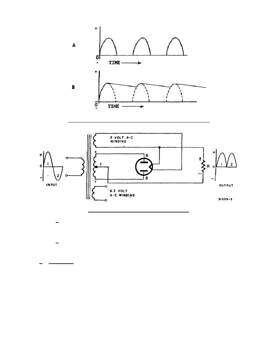
Figure 1-6.
Effect of filter capacitor on waveform.
Figure 1-7.
The full-wave rectifier.
(a) In A of figure 1-8, a junction diode is used as a half-wave
rectifier.
The output is identical with that of a diode tube
rectifier. Again, filtering will result in a near-steady dc output.
(b) In B of figure 1-8, two junction diodes are used as a full-wave
rectifier, each rectifying one-half the input signal. The resulting
output voltage can be filtered into a steady dc voltage.
b. Detectors.
(1) A simple electron-tube diode detector circuit is shown in A of figure
1-9.
The ac signal from the intermediate frequency (IF) amplifier is
rectified by the diode.
The remaining IF carrier is filtered but if
the circuit by capacitor C1. The final audio-frequency (AF) wave form
is developed across the volume control and sent to the AF amplifier.
(2) The circuit in B of figure 1-9 is similar to the circuit in A.
The
junction diode passes only the forward voltage (rectifies), and this
portion of the IF carrier is again filtered out by C1 leaving the AF to
be amplified for listening.
309 L1
9


 Previous Page
