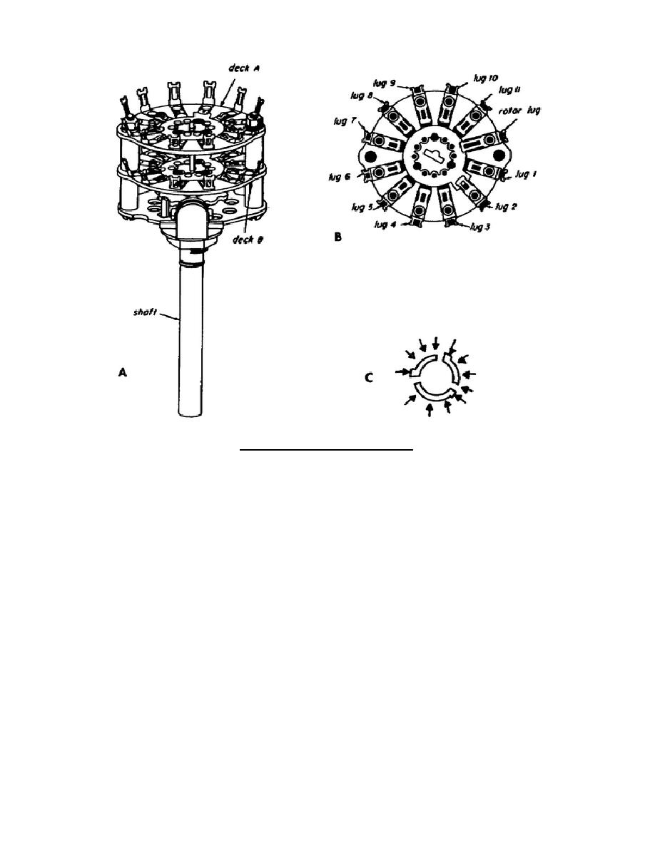
Figure 3-13.
Wafer switch.
are used between chassis where it would be impractical to solder each wire between
chassis. In each case, a socket and plug are used. Some connectors may be used to
connect only one lead, others to connect over a hundred leads.
The type of
connector used depends on the application.
There are thousands of connectors
available.
Figure 3-14 shows the schematic symbols for some of the various
connectors.
(1) The schematic symbol for a basic connector is shown in A of figure 3-
14.
The portion on the right is the socket or hole section (female
section).
The portion on the left is the plug or protruding section
(male section). Several of these symbols may be shown together, as in
B.
This indicates a multiconductor connection.
In connectors where
more than one connection is made, the symbols for individual
connections may be located at convenient points on the schematic, and
labeled.
In this case, there is usually a drawing somewhere on the
schematic to show the physical layout of the connector.
(2) The schematic symbol for a coaxial cable is shown in C of figure 3-14.
A coaxial connector combines the basic connector symbol with the symbol
for coaxial cable. A coaxial connector is shown in D.
309 L3
50


 Previous Page
