(2) Circuit boards can also be made by electroplating.
After punching
holes in the mounting board for all leads, the board is sprayed with
silver.
Ink is then stamped on the areas of silver that are to be
removed.
Next, the board is copper plated.
Not only is the circuit
pattern plated, but also the walls of the punched holes.
(This
provides an electrical connection from one side of the board to the
other.) The last step is to remove the unplated areas by brushing off
the ink and silver.
(3) A newer method of board construction is the multilayered board--a
sandwich of several layers of circuit patterns and the ceramic board.
Circuit pattern films are deposited on the board by using a vacuum
process or the silk screen process.
(4) Circuit patterns are sometimes covered with a coating of solder, tin
plating, or gold plating, to prevent corrosion and to aid soldering.
c. Termination. Standoff terminals, pads, and eyelets are used as terminals.
Wires and leads may be either insulated or uninsulated copper wire.
d. Coating. After the circuit board is completed, it is coated with any of a
variety of protective materials, or it may be encapsulated (enclosed in a
container).
e. Connection. The printed circuit is connected into the equipment by a plug
and receptacle.
These may be of the edge type, the pin and socket type, or the
forked type.
3-2.
OPERATIONAL AMPLIFIERS
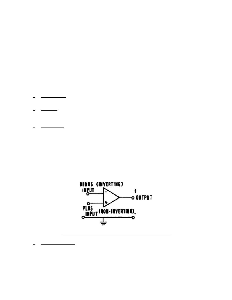
An operational amplifier (op ampl) can be considered a three-terminal device
with a common, or ground, return.
Two inputs are applied; the minus input
(inverting input) and the plus input (noninverting input). The basic op ampl shown
in figure 3-2 is a difference amplifier in that it amplifies only the difference
between the two inputs and tries to reject any signal that is common to both
inputs.
Figure 3-2.
Basic operational amplifier symbol.
a. Characteristics.
Operational amplifiers are characterized by high dc
Op ample used without feedback would be operating open loop, a rare
309 L3
40


 Previous Page
