MM0704, Lesson I
Since the same laws hold true in RL circuits as in RC circuits, the same sort of analysis may be used. The sum of the
instantaneous voltage drops around a series RL, circuit is always zero. The product of the current and the resistance
equals the voltage drop across the resistor.
In the RC circuits just studied, the capacitor opposed a sudden change of voltage across it. This caused the transient
action. In RL circuits, the inductance (coil) opposes a sudden change of current flow through it giving a transient
action. The rate at which current will change through a coil is dependent upon the voltage across the coil and the
inductance of the coil. The current through the coil will increase faster with a large voltage across it than if the voltage
were small. Also, the larger the inductance, the smaller the rate of change of current.
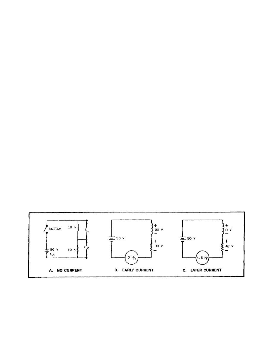
Figure 1-23A shows a series RL circuit with DC applied. At the instant the switch is closed, 50 VDC is applied to the
inductor and the resistor in series. Because the inductor has the characteristic of opposing a change in current flow,
there is no current flow through the resistor and no voltage drop across the resistor (ER= I x R = 0 x 10K). All of the
voltage must appear across the coil.
Ea
= EL + ER
50 v
= EL + OV
With 50 V across the 10-henry (10-h) inductor, which is assumed to have no internal resistance, current begins to flow
through the circuit at a rapidly changing rate.
After a short time interval, the current will have risen to 3 mamps. With 3 mamps of current, the voltage drop across
the resistor is 30 V and across the coil it is 20 V (see figure 1-23B). With the lower voltage across the coil, the current
change would be less rapid.
After another period of time, the current, since it is increasing more slowly than before, may rise to 4.2 mamps. This
would place a voltage of 42 V across the resistor, leaving only 8 V across the coil (figure 1-23C).
Since the voltage across the coil has again decreased, the rate of increase of current is again smaller. After another
period of time, the current might be 4.8 mamps. This would develop 48 V across the resistor, leaving 2 V across
Figure 1-23. Voltages Across an RL Circuit.
28


 Previous Page
