MM0704, Lesson 1
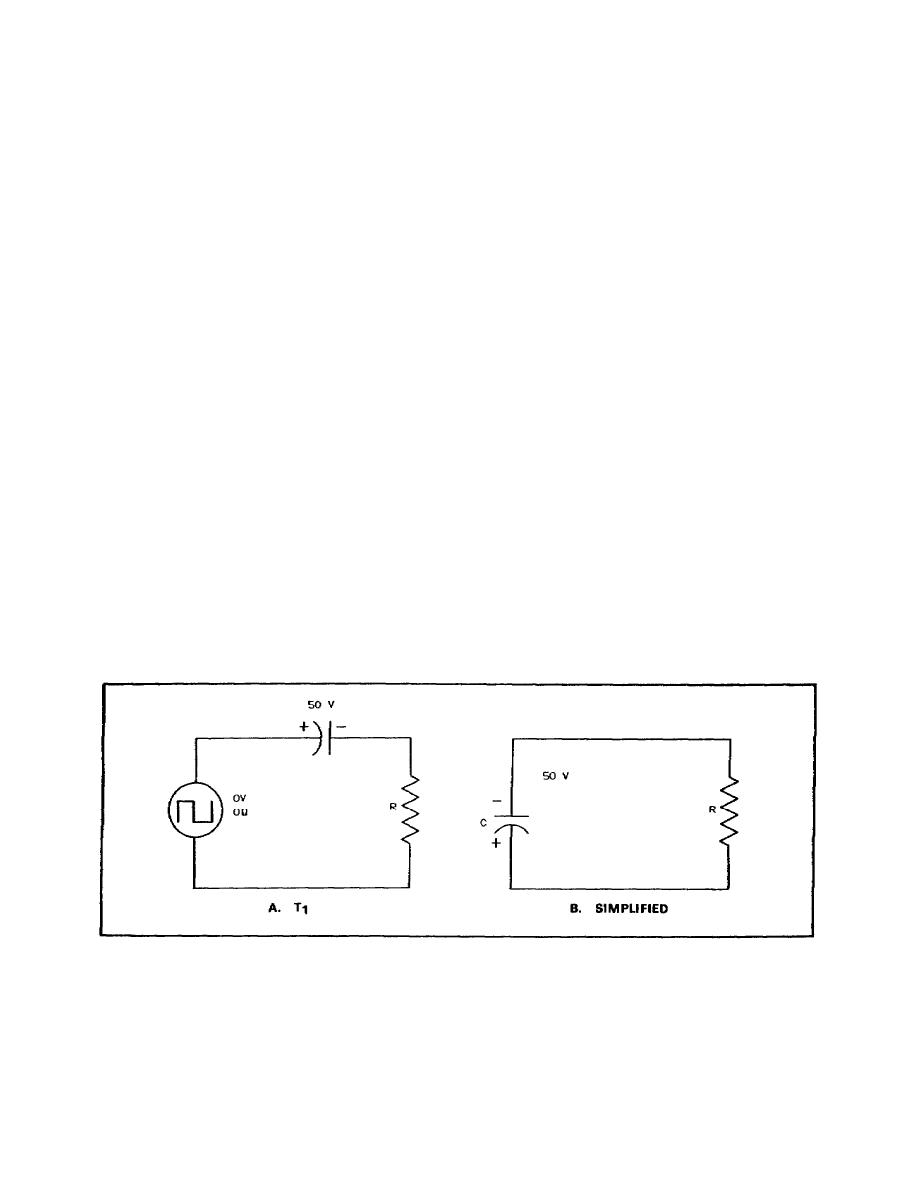
and the voltage across the resistor is zero. At T1, the input voltage drops to zero. The voltage across the capacitor is
effectively the source voltage for the resistor.
Assuming that the input source has no internal resistance, the resistor is the only component in series with the
capacitor. The capacitor begins to discharge through the resistor, reversing the direction of the original current flow
(charging current). At time T1, after the input has dropped to zero, the resistor has approximately a negative 50 V
across it (the voltage to which the capacitor is charged). Figure 1-22A shows the circuit at time T1, figure 1-22B is the
simplified equivalent.
As the capacitor voltage decreases during the discharge, the resistor voltage also decreases. Since the resistor is the
only component in series with the capacitor (figure 1-22B), EC and ER are always equal during this discharge of the
capacitor. At time T2, just before the voltage rises from zero to maximum, the capacitor has been discharging for 2,000
sec. The voltage across the capacitor and the resistor has been decreasing at an exponential rate during this time. The
value of the voltage across them at time T2 is shown in figure 1-21.
At time T2, the input voltage rises to maximum (50 V) again. A new cycle starts and the same action is repeated. The
voltages at times T2, T3, and T4 will be approximately the same as those at times T0, T1, and T2, respectively. The
continuation of these wave shapes is shown in figure 1-21. These wave shapes are from the circuit of figure 1-20 under
the conditions given; that is, with a capacitor of 0.02 fd, a 20,000-resistor, and an input having a frequency of 250 Hz.
(fd is farads.)
If the relationship between T, R, and C is changed, the shape of the resistor and capacitor voltage curves will also
change.
The RL (LR) Circuit. Wave shaping can be by RL circuits as well as by RC circuits. In RC circuits, you learned that
the transitory time was the time needed for the capacitor to charge to the applied voltage and for the current to drop to
zero. In a series RL circuit, on the other hand, the transitory time will be the time for current to build up to a maximum
value from zero or to decay from maximum to zero.
Figure 1-22. Circuit.
27


 Previous Page
