MM0704, Lesson 1
The current in a series RL circuit follows exactly the same curve in its buildup as the capacitor voltage followed in the
RC circuit. For that reason, the Universal Time Constant Chart (figure 1-18) can be used for RL circuits as well as for
RC circuits. Curve A on the graph represents current on buildup; curve B represents current on decay.
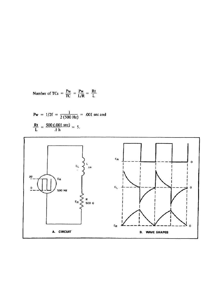
Square Wave Applied to RL Circuits. When a square wave of voltage is applied to a series RL circuit, results similar
to those from RC circuits can be expected. For example, consider the circuit of figure 1-24A with a square wave of
voltage applied. At the instant the input signal rises from zero to 20 V, the entire voltage appears across the inductor.
There is no current flowing in the circuit as yet, since the inductance opposes any change in current. The voltage
across the resistor, then, is zero. This is shown in the wave shapes of figure 1-24B.
As the current builds up in the circuit, the voltage across the resistor increases and that across the inductor decreases.
At the end of the first alternation, the number of TCs is the duration of the alternation divided by the time of 1 TC,
provided the wave is symmetrical.
In the circuit illustrated in figure 1-24,
Figure 1-24. Square-Wave Voltage in an RL Circuit.
30


 Previous Page
