while coils having iron cores are usually designed to operate at lower
frequencies such as audio or power frequencies.
(2) Inductors having more than one winding are usually
called transformers.
Their purpose is to physically isolate one circuit
from another, and to
step up or step down the voltage fed into the
winding called the
primary winding. Voltage for the circuit or
is
then taken from the
secondary winding.
(3) Samples of air-core and iron-core (magnetic-core) inductors, and iron-
core transformers are shown respectively in A, B, and C of figure 18.
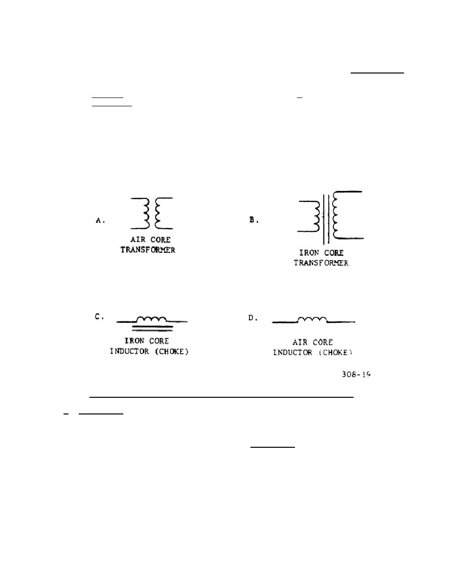
(4) Examples of the schematic symbols for these inductors can be seen in
figure 19. The air-core transformer in sketch A are for passing radio
frequencies. Sketch B shows an iron-core transformer. Sketch C is the
schematic symbol for an iron-core inductor, and sketch D is the symbol
for an air-core inductor.
Figure 19.
Schematic symbols for inductors and transformers.
b. Capacitors.
Capacitors appear in many types and sizes, depending on the
circuit application.
Most capacitors are fixed in value, but those required for
tuning applications in transmitters and receivers are made variable.
The
construction of capacitors is similar in all types in that metallic plates are
separated by an insulating material called the dielectric. In variable types, the
dielectric is usually air, but in the fixed types, many substances are suitable for
dielectric use.
Paper, mica, oil, and chemicals (electrolytic) serve as
dielectrics in different types of capacitors, the type of dielectric being chosen
to suit requirements of polarity and amount of the voltage applied to the
capacitors.
308
23


 Previous Page
