b. Principles of Operation.
Consider the four positions of the single-turn
loop and sliprings as they rotate clockwise in a uniform magnetic field produced by
the poles of an electromagnet.
(1) When the loop rotates through the position shown in A of figure 16, the
black coil side is moving toward the north pole and the white side is
moving toward the south pole.
Because the coil sides are moving
parallel to the direction of the field, no flux lines are cut and the
EMF induced in the loop is zero. This is indicated by the galvanometer
connected to the stationary carbon brushes which contact the sliprings.
(2) After the loop has rotated 90 from its initial position and is passing
through the position shown in B of figure 16, the black coil side is
moving downward and the white side upward.
Both sides are cutting a
maximum number of flux lines and the induced EMF, as indicated by the
meter, is at a positive maximum. (Meter reads to the right on positive
voltage in this case.)
(3) As the loop passes through an angle of 180 in C of figure 16, the coil
sides again are cutting no flux lines and the generated EMF is again
zero.
(4) As the loop passes through an angle of 270, as in D of figure 16, the
coil sides are cutting a maximum number of flux lines and the generated
EMF is at a negative maximum.
(5) The next 90 revolution of the loop completes the 360 revolution, and
the generated EMF falls to zero.
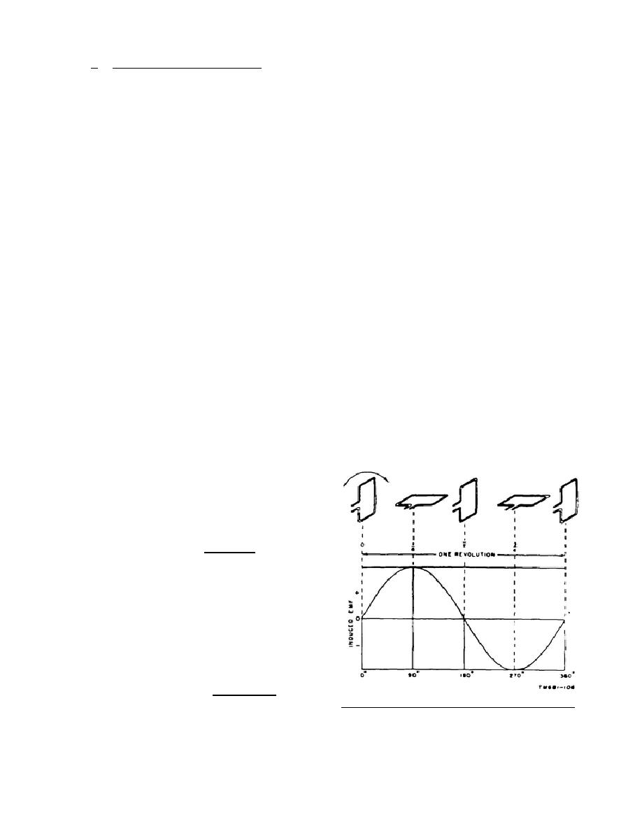
(6) The preceding facts may be
summarized as follows: As
the
loop
makes
one
complete
revolution
of
360, the generated EMF
passes from zero to a
positive maximum, to zero,
to a negative maximum, and
back
to
zero.
If
a
constant speed of rotation
is assumed, the EMF is
said to be periodic. That
is, the values of EMF
repeat
at
regular
intervals,
and
can
be
represented by a sine wave
when shown on a graph.
Figure 17 contains a graph
that shows the portion of
a sine wave representing
the EMF produced in one
revolution of a wire loop
in a magnetic field. This
portion is one cycle of
the voltage.
Note that
Figure 17.
Generation of a sine wave.
the
308
21


 Previous Page
