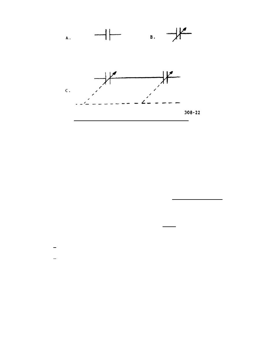
Figure 22.
Schematic symbols for capacitors.
counter EMF produced.
The rate of change of the magnetic flux is
controlled by the frequency of the applied voltage. A coil intended to
be used at high frequencies can therefore be smaller than one intended
for low frequencies for the same amount of opposition (counter EMF) to
current flow. The difference in size of the coils will be evident if
you have occasion to compare the RF inductors of a television receiver
with those in a broadcast radio receiver.
(3) In the foregoing discussions, the opposition offered to a specific
change of ac by an inductance was measured at any given instant in
terms of counter EMF, the voltage opposing the applied voltage. In dc
circuits, however, any opposition to current flow is termed resistance
and is measured in ohms. In ac circuits, therefore, it is convenient
to measure inductive opposition in ohms rather than in volts of counter
EMF. This type of ac opposition is called inductive reactance and is
assigned the symbol XL to distinguish it from dc resistance, R. From
here on, we will refer to the opposition offered by an inductance to ac
flow as inductive reactance XL.
(4) The unit of measure of inductance is the henry (h). Since small values
of inductance are used in radio circuits, it is customary to rate the
inductance value in millihenries or microhenries.
(a) 1 millihenry = 1/1,000 henry = 0.001 henry = 1 x 10⁻³ henry.
(b) 1 microhenry = 1/1,000,000 henry = 0.000,001 henry = 1 x 10⁻⁶ henry.
(5) Current through an inductance does not increase in proportion to the
change of voltage across the inductance. This is due to the fact that
a time delay exists in the buildup of the magnetic field to the maximum
value. To explain this delay time, it is customary to say
308
26


 Previous Page
