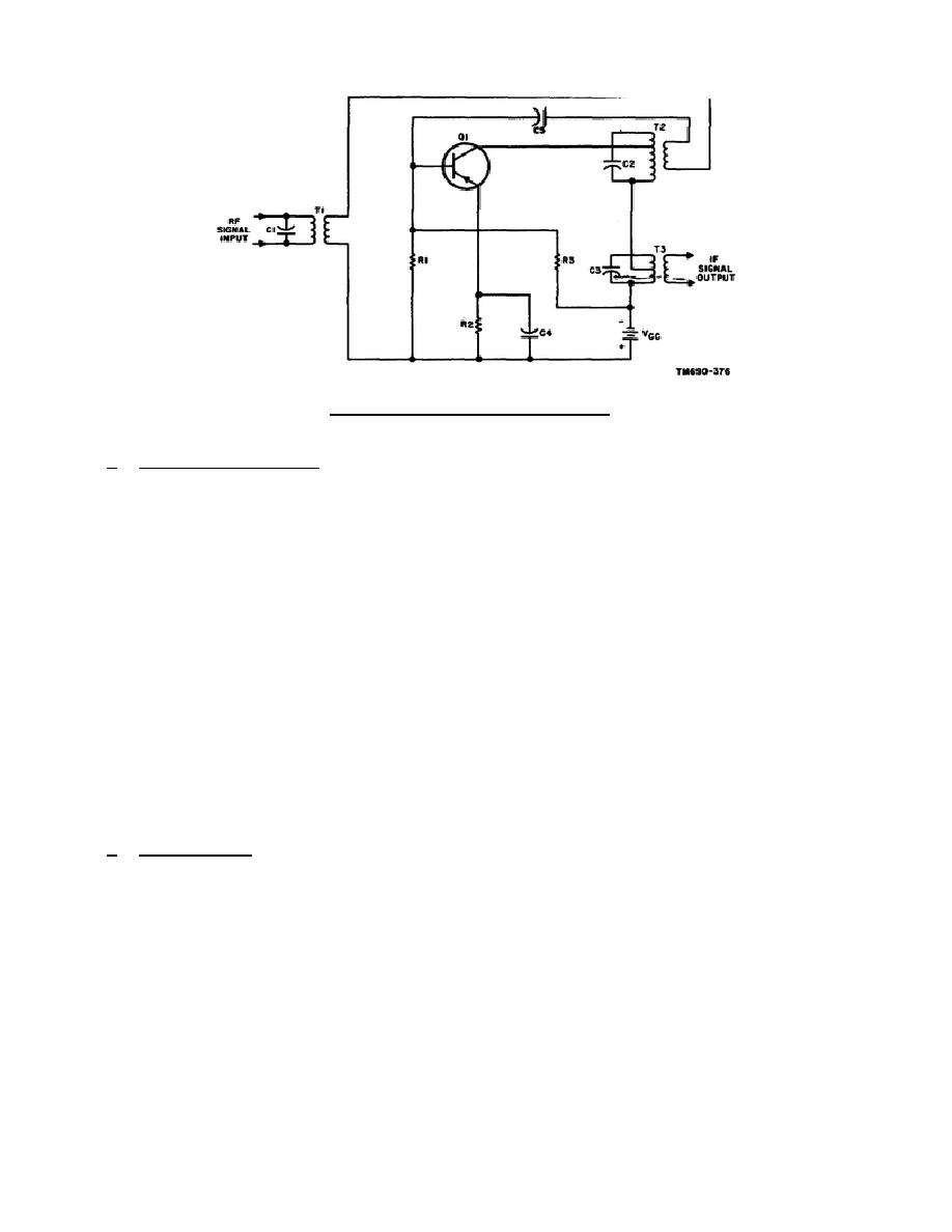
Figure 2-4.
Converter circuit.
b. Component Functions. Capacitor C1 and the primary of transformer T1 form a
parallel resonant circuit for the radio frequency, which is coupled through the
transformer to the base circuit of converter Q1. Resistor R1 develops the emitter-
base bias, and resistor R3 is a voltage-dropping resistor.
Resistor R2 is the
emitter-swamping resistor, and capacitor C4 is a bypass for the radio frequency.
Capacitor C2 and the primary of transformer T2 form a parallel resonant circuit for
the oscillator frequency.
The secondary of transformer T2 provides the required
feedback for the oscillator portion of converter Q1. Capacitor C5 is a dc blocking
capacitor. Capacitor C3 and the primary of transformer T3 form a parallel resonant
circuit for the intermediate frequency, which is coupled through the transformer to
the following stage. The primaries of transformers T2 and T3 are tapped to obtain
the desired selectivity.
2-5.
LC OSCILLATORS
The resonant features of inductance-capacitance (LC) circuits make them very
suitable for frequency determination.
Moreover, such circuits are readily
adaptable for feedback arrangements.
Successively, the following types will be
treated: tickler-coil (Armstrong), Hartley, tuned-collector tuned-base, Colpitts,
and crystal-controlled oscillators.
a. Tickler-Coil.
The circuit shown in figure 2-5 is practically self-
explanatory inasmuch as the requirements for oscillation are apparent.
The
amplifying device and power supply Vcc are readily seen. Regenerative feedback is
obtained by the transformer action between L1 and L2. The dots at opposite ends of
these inductors indicate the phase inversion required for regeneration.
Finally,
frequency is determined by the collector tank circuit (L2 and C2).
16


 Previous Page
