d. Converter Output.
The input and output waveforms of a converter stage are
shown in B of figure 2-1.
Frequency F2 is applied to the converter stage, and
frequency F1 is generated within the converter stage. The two frequencies present
in the converter stage produce four prominent frequencies in the output.
The
frequencies is represented by F1 plus F2.
The difference is represented by F1
minus F2.
2-2.
INJECTION OF OSCILLATOR FREQUENCY
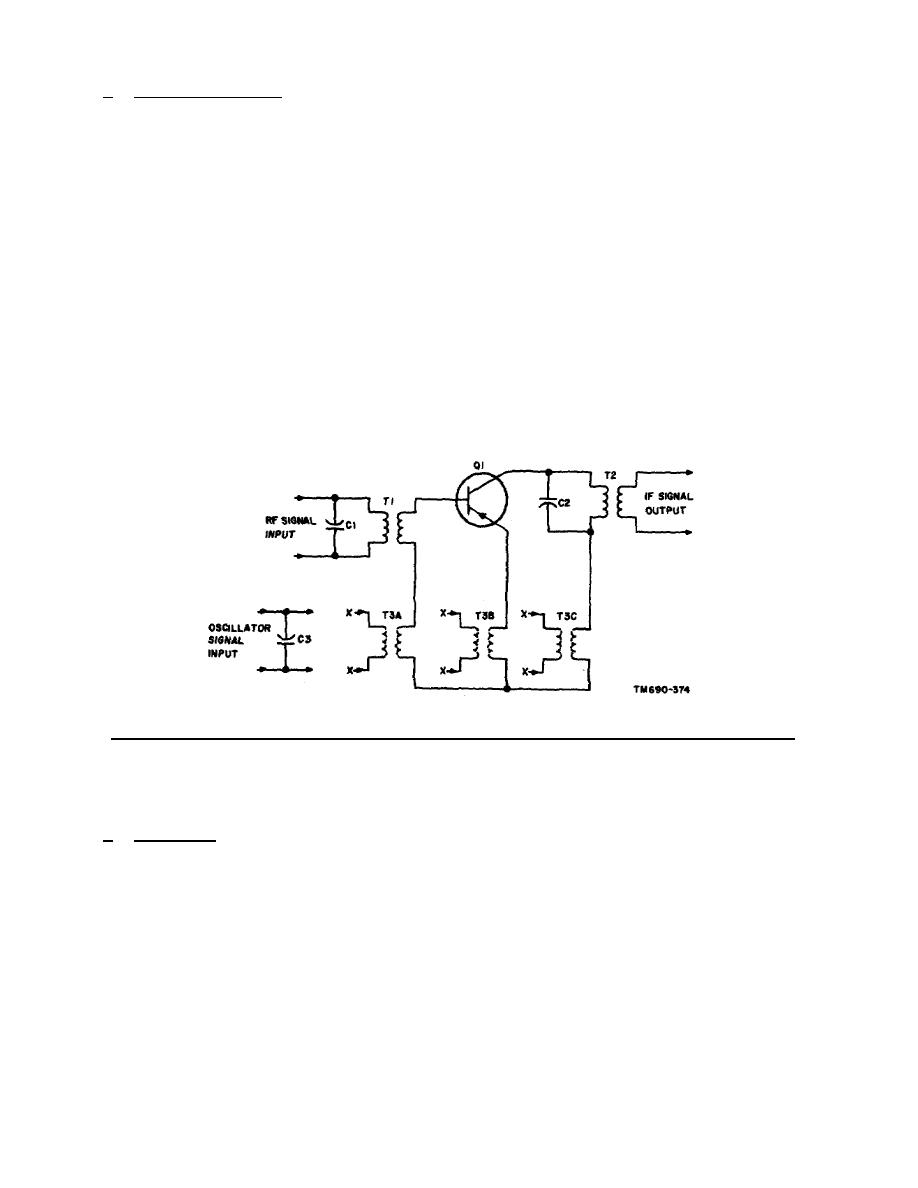
As shown in figure 2-2, the oscillator frequency can be fed to the base, the
emitter, or the collector circuit of a mixer stage.
The oscillator frequency is
coupled through T3A, T3B, or T3C to the base, the emitter, or the collector,
respectively.
Capacitor C1 and the primary of transformer T1 form a parallel
resonant circuit for the radio frequency that is coupled to the base circuit of
mixer Q1.
Capacitor C3 and the primary of transformer T3A, T3B, or T3C form a
parallel resonant circuit for the oscillator frequency.
Capacitor C2 and the
primary of transformer T2 form a parallel resonant circuit for the intermediate
frequency which is coupled through the transformer to the following stage.
Figure 2-2.
Methods of injecting an oscillator frequency into a mixer stage.
2-3.
MIXER
a. Operation.
A schematic diagram of a mixer stage with typical values of
components is shown in figure 2-3. The RF signal is 1 MHz; the oscillator signal,
1.5 MHz; the IF signal, 500 kHz.
Emitter injection is employed to couple the
oscillator signal into the mixer circuit.
The radio frequency injected into the
base circuit and the oscillator frequency injected into the emitter circuit are
heterodyned in mixer Q1. The intermediate frequency is selected by the collector
tank circuit. The intermediate frequency is then coupled through transformer T3 to
the following stage.
14


 Previous Page
