(2) Although Hartley oscillators
are usually designed to have
a tapped coil and inductive
coupling,
many
other
oscillatory
systems
that
operate basically as Hartley
oscillators do not have such
coupling.
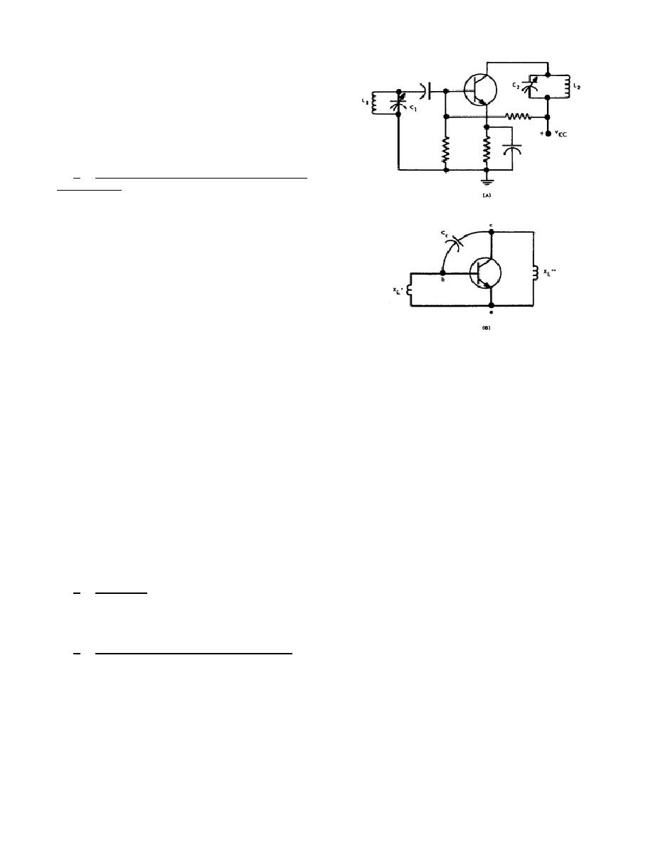
c. Tuned-Collector
Tuned-Base
Oscillator. Looking at A of figure 2-
7, we find a circuit that could be an
RF or IF amplifier.
However, with
positive feedback, the circuit becomes
an oscillator.
(1) We know that a parallel tank
circuit presents an inductive
reactance
for
frequencies
lower
than
the
resonant
frequency.
Therefore, for
some
frequency
below
the
resonant frequency, the input
tank (L1 and C1) can be
Figure 2-7. Tuned-collector tuned-
represented in B of figure 2-
base oscillator.
7 by XL.
Likewise, the
output tank (L2 and C2) can
be
represented
by
XL.
Between points c and b is the
collector-to-base interelectrode capacitance CC, as shown.
Now compare
the circuit in B of figure 2-7 with that of the Hartley oscillator in B of
figure 2-6.
They are identical.
Thus the tuned-collector tuned-base
oscillator operates to produce a sine-wave signal by virtue of the fact it
is essentially a Hartley arrangement.
(2) Now you can appreciate why an RF or IF amplifier may break into
oscillation. If CC is sufficient in value (or an additional capacitor is
connected from collector to base), the generation of a sinusoidal signal
of a given frequency will result.
The generated frequency will
necessarily be less than the resonant frequency of both the input and
output tanks since both tanks must appear inductive to the signal.
d. Colpitts.
Instead of connecting the emitter to the inductance of a tank
circuit as is done for the Hartley, in the Colpitts oscillator the emitter is
connected between two capacitors. This arrangement constitutes the distinguishing
difference between a Colpitts and a Hartley oscillator.
e. Crystal-Controlled Oscillators.
A piezoelectric crystal can behave as a
high-Q circuit.
The electrical equivalent network for such a crystal is
illustrated in A of figure 2-8.
This network will have a series resonant point
when XL = XC1, and a parallel resonant point when XL = XC1 + XC2 Part B of figure
2-8 depicts a typical impedance-versus-frequency plot.
Observe that at series
resonance the crystal is practically a short circuit.
19


 Previous Page
