c. For an illustration of the effect of the meter sensitivity on the accuracy of
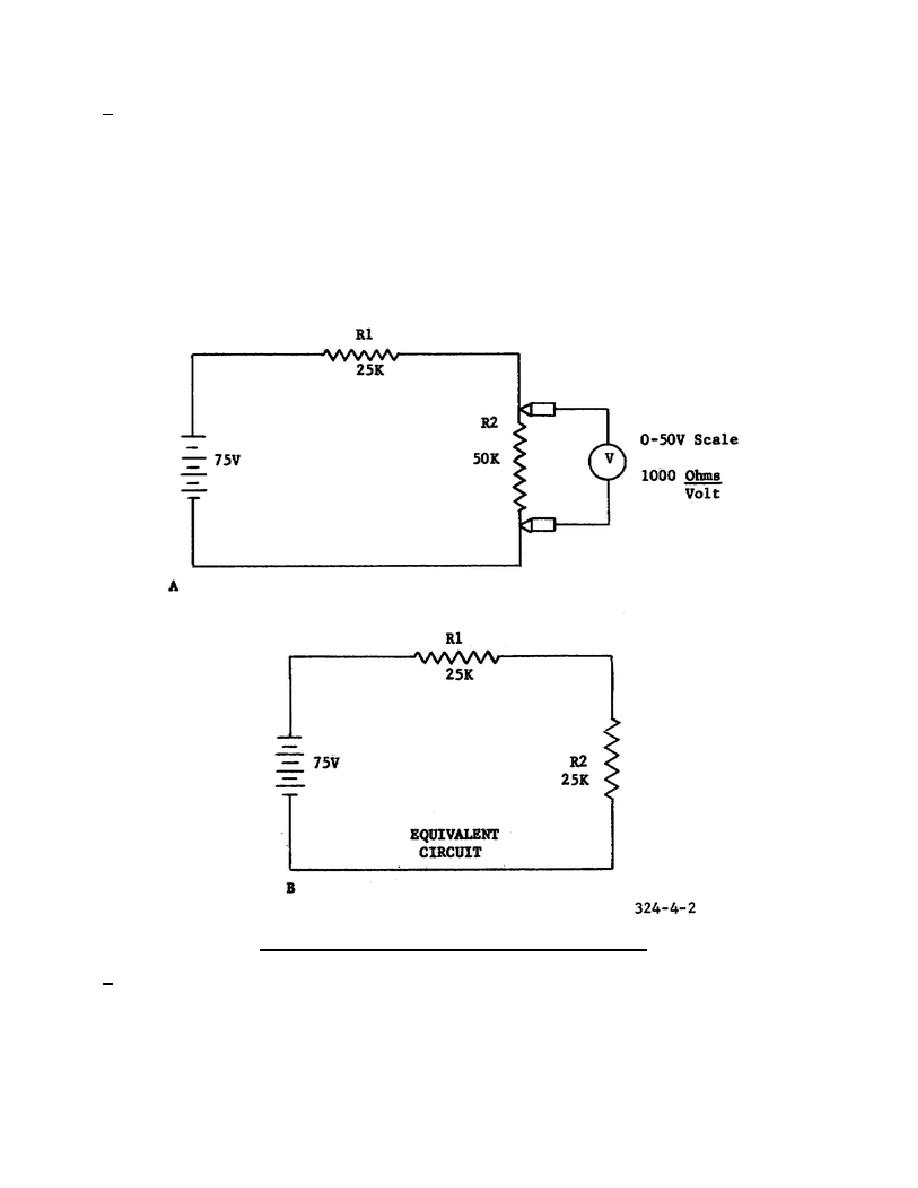
voltage readings in high-resistance circuits, refer to figure 4-2.
Normally, the
two series resistors (R1 and R2) across the voltage source would divide the voltage
in the ratio of 1-to-2, causing the voltmeter to read 50 volts (A of fig. 4-2).
However, the voltmeter appears as a 50K-ohm resistor in parallel with R2.
This
effectively reduces the equivalent resistance of R2 and causes the voltage to be
divided in the ratio of 1-to-l (B of fig. 4-2). The voltmeter will now read 37.5
volts.
It should be apparent after studying the diagram that, compared with the
meter resistance, the higher the resistance in the circuit, the greater the
"loading' effect of the voltmeter.
Sometimes the loading effects of a voltmeter
can be reduced by switching the meter to the next higher range because the addition
of a multiplier increases the input resistance of the meter.
Figure 4-2.
Loading effects of a voltmeter.
d. Although a 20,000-ohm-per-volt voltmeter may be used to align a receiver, the
relatively small output voltages can be more accurately measured by the VTVM
because of its high input resistance.
The input resistance of a VTVM can be as
high as the internal resistance between the grid and cathode
41


 Previous Page
