of an electron tube. In practice, however, the input resistance is standardized at
approximately 10 megohms, which produces negligible loading.
Section II.
TRANSISTORIZED RECEIVER
4-4.
GENERAL
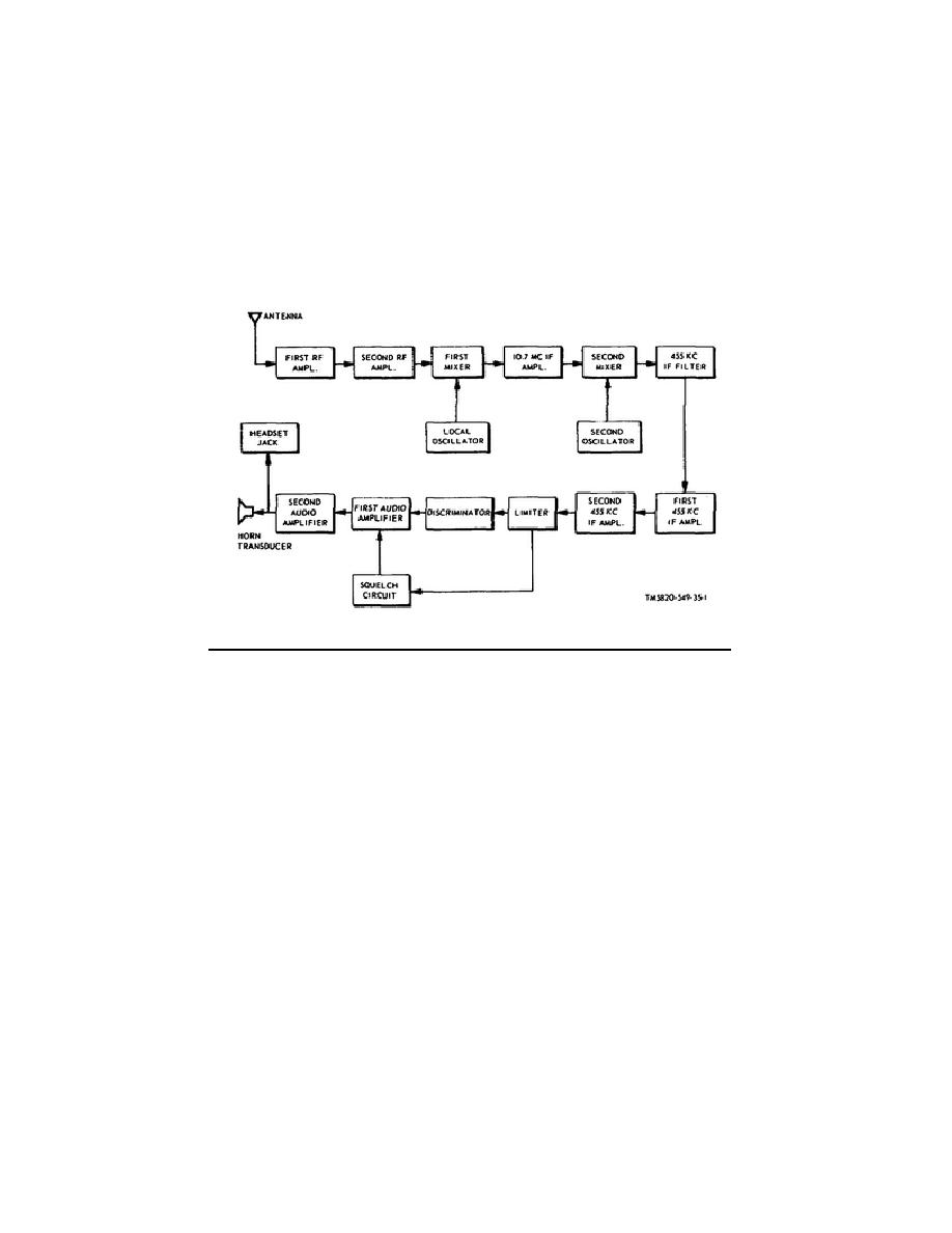
Radio Receiving Set AN/PRR-9 employs 14 transistors and six diodes in a double-
conversion type of superheterodyne circuit. The block diagram of the receiver is
shown in figure 4-3 and the schematic diagram is shown in figure 4-4.
Figure 4-3.
Radio Receiving Set AN/PRR-9, block diagram.
4-5.
ANTENNA AND RF CIRCUITS
The antenna for the AN/PRR-9 is an 18-inch stainless steel whip-type antenna.
Miniature loading coil L1, connected in series with the antenna, is used for tuning
out antenna capacitance.
Operating the two RF amplifiers (Q1 and Q2) in the
common-base configuration eliminates the need for neutralization of the circuits
and minimizes the changes in RF gain that are caused by variations in supply
The RF selectivity is obtained through the use of three tunable tank
circuits (Cl-Tl, C2-T2, and C3-T3).
4-6 FIRST CONVERSION OSCILLATOR
The first conversion oscillator (Q4) employs a removable miniature crystal in a
series-resonant configuration. The oscillator is operated on the low side of the
received signal, that is, 10.7 MHz below the RF input signal.
A miniature
powdered-iron toroid (T5) and an air-trimmer-type capacitor (C7)
42


 Previous Page
