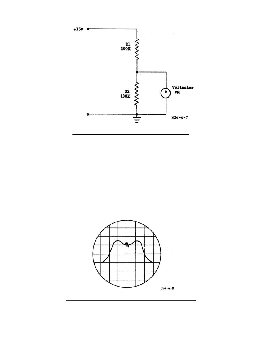
Figure 4-7.
Circuit loading with a voltmeter.
14. Assume that a visual alignment is to be made of the final IF amplifier (V8)
in the receiver shown in figure 153 of TM 11-668.
The oscilloscope is to be
connected with its vertical-deflection terminals between the grid of V9 and ground,
and the horizontal-deflection terminals connected to a sweep generator.
A signal
generator and a marker generator are to be connected to the grid of V8.
The
oscilloscope presentation shown in figure 4-8 indicates that the circuit being
aligned is
a. overcoupled with a marker showing the IF limits.
b. critically coupled with a marker showing the IF limits.
c. overcoupled with a marker showing the IF center frequency.
d. critically coupled with a marker showing the IF center frequency.
Figure 4-8.
Oscilloscope display for IF alignment.
51


 Previous Page
