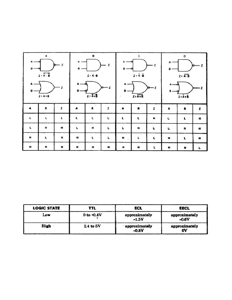
inputs are HIGH. Negative NAND and NOR logic is illustrated in figure 1C.
In this case a HIGH can only be present at the 2 terminal when both A and B
are LOW. The exact opposite of this is shown in figure 1D where a LOW state
can only be produced at the Z output when both A and B are HIGH. These are
called Positive Logic NAND and NOR.
Figure 1.
Logic comparison diagram.
Three types of logic are used in the Model 5345A; Transistor-
Transistor Logic (TTL), Emitter-Coupled Logic (ECL), and Emitter-Emitter-
Coupled Logic (EECL). The voltage associated with the High and Low states
is different for each of these as shown in table 1. It is very important to
keep this in mind when troubleshooting as a High logic state in one circuit
could easily be mistaken for a Low in another and vice-versa.
Table 1.
Logic levels.
36


 Previous Page
