connected to this jack for very precise observation of zero beat when
measuring pulsed RF signals.
Thumbwheel switches automatically perform harmonic computation for the
counter by extending the counter's gate time by the factor N. In this way,
the counter's readout is the actual input frequency.
N can be determined
exactly, and verified, by simple procedures to be described later in this
lesson.
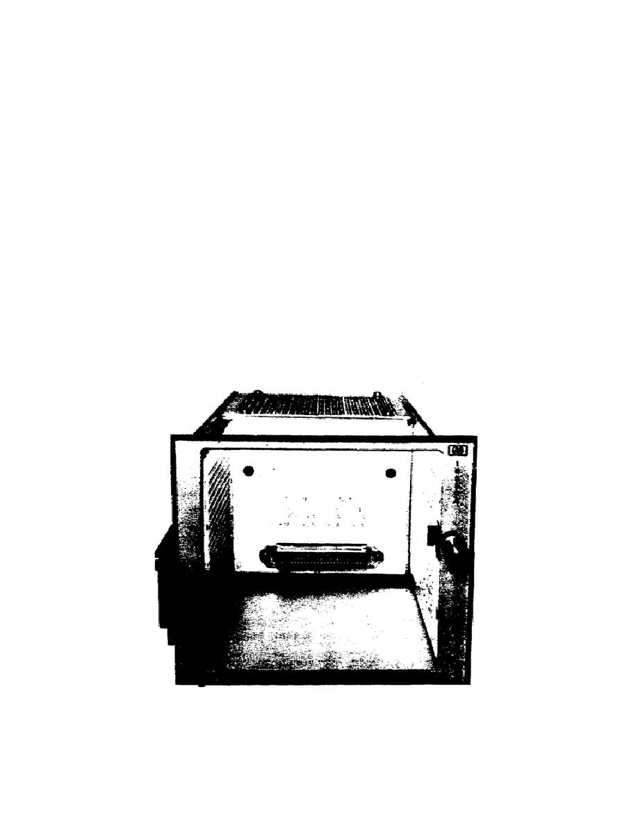
b. Installation. In order for the transfer oscillator to be used with
the Model 5345A counter, it is necessary to first install a Model 10590A
plug-in adapter (figure 2) in the counter's plug-in receptacle. The plug-in
adapter converts the counter's power supplies for use with the 5257A and
numerous other plug-ins of the same instrument family.
Additionally, two
channels of amplification and signal conditioning are provided. Frequency
type plug-ins use one of these channels while time interval plug-ins use
both: one as a start channel and the other as a stop channel. The transfer
oscillator plug-in supplies a gate extension or N Factor which is used by
the 5345A to correctly process the measurement. The 10590A processes the N
Factor and provides compatibility between the plug-in and the 5345A.
To
install these units in the counter, turn the adapter retaining latch fully
counter-clockwise. Then push the unit firmly into the compartment until the
front panel of the plug-in is flush with the front panel of the adapter and
counter. Then turn the retaining latch clockwise until it is tight.
Figure 2.
Model 10590A plug-in adapter.
61


 Previous Page
