8.
The shielded pair.
The shielded pair type transmission line shown in Part B of Figure 3
is used mainly for power transmission of frequencies up to 30 megahertz.
Above 30 megahertz, excessive losses occur in the insulating material. The
shielded pair has low radiation losses because the two conductors are
completely surrounded by a copperbraid which acts as a shield.
A rubber
covering surrounds the outside copper shield. This type of line can be run
close to metal surfaces without serious losses.
The shielded pair is
available in characteristic impedances of approximately 40 to 150 ohms.
9.
The parallel pair.
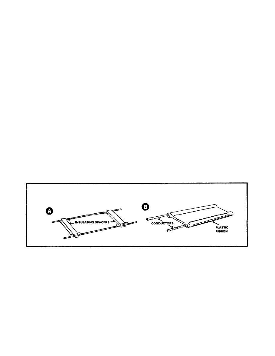
a. There are two parallel pair types: the open two-wire line shown in
Part A of Figure 4; and the insulated two-wire line, commonly known as
ribbon parallel line, shown in Part B of Figure 4. The open two-wire line
uses air as the dielectric.
The two wires are kept at the same distance
apart for the entire length by insulating bars called spacers or spreaders.
The spacing between conductors may vary from 2 to 6 inches, depending on the
voltage between the two wires and the frequency of the applied voltage.
Closer spacing is preferable at higher frequencies to reduce radiation
losses.
b. The insulated two-wire line shown in Part B of Figure 4 uses a
solid, flexible dielectric such as polyethylene.
This type is used to
connect a television receiving antenna to a TV set. Its low cost, low loss,
and simplicity make it ideal for such installations.
Figure 4.
Two-Wire Parallel Conductor Transmission Line.
c. In general, parallel conductor lines have advantages of low cost,
and high efficiency, because of their low losses. Also, they are easy to
construct and install.
Characteristic impedances range from approximately
75 to 500 ohms. The parallel conductor line can be used for frequencies up
to 200 megahertz.
Above 200 megahertz, high radiation losses occur,
particularly near metal surfaces.
5


 Previous Page
