17.
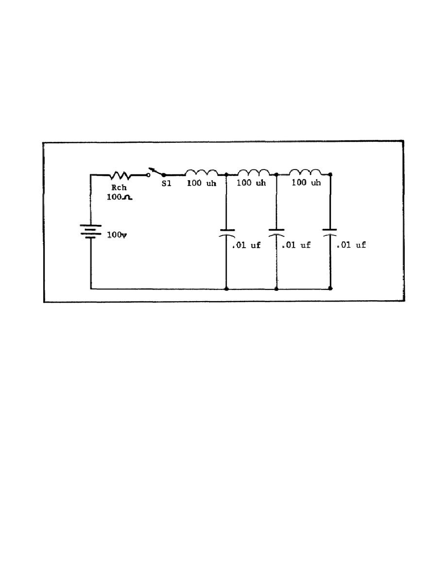
Six microseconds after switch S1 is closed in the ATL shown in Figure
49, the voltage across the charging resistance will be
a.
equal to zero.
b.
equal to the voltage across Rc.
c.
greater than the voltage across Rc.
d.
one-half the value of the voltage across Rc.
Figure 49. Charging ATL.
18.
Assume that the pulse-forming network shown in Figure 50 is being
designed to produce a rectangular output pulse.
To produce the
desired pulse, the circuit's applied voltage will be equal to
a.
100 volts.
b.
400 volts.
c.
200 volts.
d.
300 volts.
59


 Previous Page
