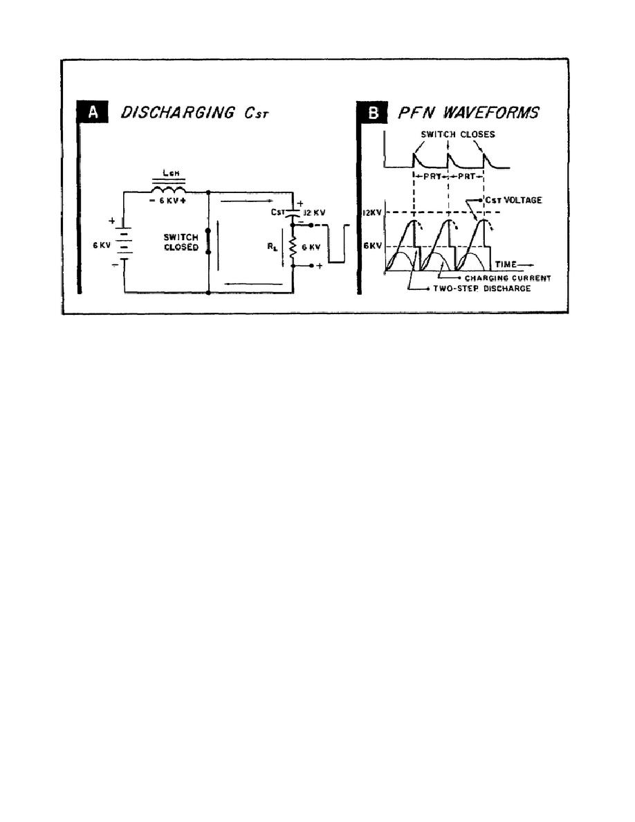
Figure 61.
The Discharge Cycle.
c. To get the largest pulse possible across the load, then, the switch
must close when there is maximum voltage across Cst. This means that the
inductance (Lch) of the charging choke and the capacitance (Cst) of the PFN
must resonate at one-half the frequency of the PRF. This also means that
the radar set can operate at only one PRF which is dependent on the values
of Lch and Cst.
However, by adding a diode, called a charging diode, in
series with the charging choke and the PFN, the pulse repetition frequency
can be changed. Let's see how this is done.
4.
Charging diode prevents discharge of PFN.
a. Figure 62 shows the operation of a DC resonant charging circuit with
a charging diode in series with Lch and Cst. Part A shows the equivalent
circuits of the charge and discharge cycles; Part B shows the waveform
analysis. Again, keep in mind that Cst represents the pulse-forming network
and the switch takes the place of the HYDROGEN THYRATRON. The load in not
shown in the charge cycle because its impedance is small compared to that of
Lch.
b. Look at the charging cycle in Part A, first.
At the instant the
switch opens, Cst starts to charge to the source voltage.
The plate of
charging diode, V2, is positive with respect to its cathode. Therefore, it
conducts heavily, charging Cst through choke, Lch.
Because the induced
voltage of Lch is in series with the source voltage, Cst charges to 12KV.
With Cst charged to 12KV, there is no longer a difference of potential
across the diode, so it stops conducting.
Now, however, Cst cannot
discharge because both V2 and the switch are open circuits. Consequently,
Cst holds its charge until the switch closes.
77


 Previous Page
